


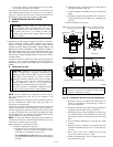
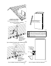
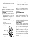
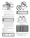
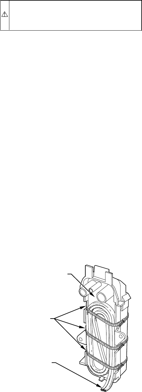
4. Wrap field drain pipe with remaining heat tape, approxi-
mately 1 wrap per ft.
5. When using field-supplied heat tape, follow heat tape
manufacturer’s instructions for all other installation guide-
lines.
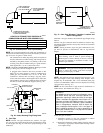
SEQUENCE OF OPERATION
CAUTION: Furnace control must be grounded for
proper operation, or control will lock out. Control is
grounded through green wire routed to gas valve and
burner box screw.
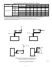
Using schematic diagram, follow sequence of operation through
different modes. (See Fig. 26.) This furnace has a new control
system. Read and follow wiring diagram carefully.
NOTE: If 115-v power supply to furnace or blower access panel
switch is interrupted during a call for heat, blower operates for 90
sec when power is restored before heating cycle is resumed.
I. HEATING MODE
When wall thermostat "calls for heat," R-W circuit closes. Furnace
control performs a self-check, verifies pressure switch contacts are
open, and starts inducer motor.
1. Prepurge period—As inducer motor comes up to speed,
pressure switch contacts close to begin a 15-sec prepurge
period.
2. Ignitor warm up—At end of prepurge period, ignitor is
energized for a 17-sec ignitor warm-up period.
3. Ignition sequence—When ignitor warm-up period is com-
pleted, gas valve opens, permitting gas flow to burners
where it is ignited. After 5 sec, ignitor is de-energized and
a 2-sec flame-sensing period begins.
HUM terminal on control center is energized with gas
valve. See Accessories — Humidifier section.
4. Flame sensing—When burner flame is sensed, control
begins blower on delay period and continues holding gas
valve open.
If burner flame is not sensed, control center de-energizes
gas valve and ignition sequence is repeated.
NOTE: Ignition sequence repeats 3 additional times before a
lockout occurs. Lockout automatically resets after 3 hr or can be
manually reset by turning off 115v (not at thermostat) for 3 sec
minimum, then turning it on again.
5. Blower on delay—Sixty sec after burner flame is proven,
blower motor is energized on heating speed. Simulta-
neously, electronic air cleaner terminal EAC-1 is energized.
6. Blower off delay—When thermostat is satisfied, circuit
between R-W is opened, de-energizing gas valve (stopping
gas flow to burners) and humidifier. Blower motor and
electronic air cleaner remain energized for 135 sec.
7. Post purge—Inducer motor remains energized 15 sec after
burners are extinguished.
II. COOLING MODE
When thermostat "calls for cooling," R-G and R-Y circuits close.
R-Y circuit starts outdoor condensing unit, and combined R-Y and
R-G circuit starts furnace blower motor on cooling speed. Elec-
tronic air cleaner EAC-1 terminal is energized with 115v whenever
blower is operating.
When thermostat is satisfied, R-G and R-Y circuits are opened,
furnace blower continues operating on cooling speed for an
additional 90 sec.
III. CONTINUOUS BLOWER MODE
When R-G circuit is made, blower motor operates on heating
speed.
NOTE: Electronic air cleaner EAC-1 terminal is energized with
115v whenever blower is operating.
If a "call for heat" (R-W) occurs while thermostat is in continuous
blower mode, blower stops to allow furnace heat exchangers to
heat up more quickly, then restarts at end of blower on delay
period of 60 sec.
Blower reverts to continuous operation after heating cycle is
completed.
If a "call for cooling" (R-Y) occurs while thermostat is in
continuous blower mode, blower changes from continuous blower
speed (heating speed) to cooling speed.
When thermostat cooling call is satisfied, R-Y opens and blower
operates an additional 90 sec at cooling speed before reverting
back to continuous operation (heating speed).
IV. HEAT PUMP MODE
When installed with a heat pump, furnace control automatically
changes blower on delay timing sequence to avoid no blower
operation time during demand defrost cycles. When R-W and R-Y
or R-W, R-Y, and R-G thermostat inputs are received at the same
time at furnace control center, control starts blower in heating
speed. Then a gas heat mode begins. Blower remains operating at
heating speed for 15 sec or until end of prepurge period, then
blower shuts off until end of ignitor warm up and trial for ignition
periods (a total of 24 sec). Blower restarts at heating speed.
When R-W thermostat call disappears, control completes inducer
post-purge period (15 sec) and changes to cooling speed after a
2-sec delay.
If R-W, R-Y, and R-G thermostat signals should disappear
simultaneously, blower remains on for heating blower off delay
period of 135, and the inducer goes through 15 sec post-purge
period. If R-W and R-Y thermostat signals should disappear,
leaving R-G thermostat signal, blower remains on in heating speed
and inducer remains on for 15 sec to complete post-purge period.
Control initiates a 90-sec blower only on period before starting
another heat pump cycle if there is a power interruption. Anytime
control senses false flame, control locks out of heating mode. This
reaction occurs because control ignores W input due to false flame
signal and, as a result, sees only Y input and goes into cooling
mode blower off delay. All other control functions remain in
standard format.
NOTE: EAC-1 terminal is energized whenever blower operates.
HUM terminal is only energized when gas valve is energized.Fig. 37—Condensate Trap Heat Tape
A93036
CONDENSATE TRAP
WIRE TIE(S)
HEAT TAPE
(3 WRAPS MINIMUM)
—31—