


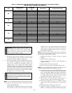

V. COMPONENT TEST
A. Component Test Sequence
NOTE: All components are functionally operated except the gas
valve.
When component test is initiated, the following sequence of events
occurs:
1. LED flashes a status code 4 times.
2. Inducer motor starts and continues to run for remainder of
component test.
3. Hot surface ignitor is energized for 15 sec, then de-
energized.
4. Main blower operates at cooling speed for 10 sec, then turns
off.
5. Main blower operates at heating speed for 10 sec, then turns
off.
6. Inducer motor stops.
Component test can be initiated by one of the following proce-
dures.
B. Initiating Component Test By Removing Main Limit
Switch Wire
NOTE: NO thermostat signal may be present at control center
and all blower time delay off periods must be completed.
1. Leave 115-v power to furnace turned on.
2. Remove main furnace door.
3. Look into blower access panel sight glass for current LED
status.
NOTE: Leave blower access panel installed to maintain power to
control center to view current LED status.
4. BRIEFLY remove either wire from the main limit switch
until the LED goes out, then reconnect it.
CAUTION: Make sure limit switch wire does not con-
tact any metallic component such as the gas valve. If wire
is shorted, 3-amp fuse on control center will blow.
NOTE: If wire to main limit is disconnected longer than 4 sec, the
control senses limit circuit is open. Main blower will start and fault
retrieval request will be ignored.
5. When above items have been completed, the component
test sequence will occur as described in the Component Test
Sequence section above.
NOTE: Be sure to record the status code which is flashed 4 times
at start of component test for further troubleshooting.
6. After component test is completed and LED is ON continu-
ously indicating the furnace is ready to operate when a
signal from the thermostat is received, replace main furnace
door.
C. Initiating Component Test By Jumpering Control
TEST Terminal
1. Remove main furnace door.
2. Remove blower access panel.
3. Manually close blower access panel door switch. Use a
piece of tape to hold switch closed.
WARNING: Blower access panel door switch opens
115-v power to control center. No component operation
can occur. Caution must be taken when manually closing
this switch for service purposes. Failure to follow this
warning could result in electrical shock, personal injury,
or death.
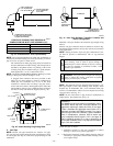
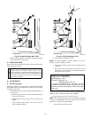
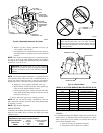
4. BRIEFLY short (jumper) TEST, 1/4-in. quick-connect
terminal on control center (adjacent to the LED diagnostic
light) and the C
OM terminal on thermostat connection block.
(See Fig. 26.)
NOTE: If TEST to C
OM terminals are jumpered longer than 2 sec,
LED will flash rapidly, and retrieval request will be ignored.
5. When above items have been completed, the component
test sequence will occur as described in the Component Test
Sequence section above.
NOTE: Be sure to record the status code which is flashed 4 times
at start of component test for further troubleshooting.
6. After component test is completed and furnace is operating
properly, release blower access panel door switch, replace
blower access panel, and replace main furnace door.
START-UP PROCEDURES
I. GENERAL
1. Furnace must have a 115-v power supply properly con-
nected and grounded. Proper polarity must be maintained
for correct operation.
NOTE: Proper polarity must be maintained for 115-v wiring. If
polarity is incorrect, control center fault indicator light will flash
rapidly and furnace will not operate.
2. Thermostat wire connections at terminals R, W, G, and Y
must be made at 24-v terminal block on control center.
3. Natural gas service pressure must not exceed 0.5 psig
(14-in. wc), but must be no less than 0.16 psig (4.5-in. wc).
4. Blower access panel must be in place to complete 24-v
electrical circuit to furnace.
CAUTION: These furnaces are equipped with a manual
reset limit switch in burner box. This switch will open if
an overheat condition (rollout) occurs in burner enclo-
sure. Correct inadequate combustion-air supply or im-
proper venting condition and reset switch. DO NOT
jumper this switch.
Before operating furnace, check each manual reset switch for
continuity. If necessary, press button to reset switch.
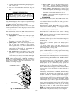
II. PRIME CONDENSATE TRAP WITH WATER
CAUTION: Condensate trap must be PRIMED or
proper draining may not occur. The condensate trap has 2
internal chambers which can ONLY be primed by pour-
ing water into the inducer drain side of condensate trap.
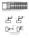
1. Remove upper inducer housing drain connection cap. (See
Fig. 38.)
2. Connect field-supplied 1/2-in. ID tube to upper inducer
housing drain connection.
3. Insert field-supplied funnel into tube.
4. Pour 1 quart of water into funnel/tube. Water should run
through inducer housing, overfill condensate trap, and flow
into open field drain. (See Fig. 39.)
—32—