


WARNING: Inducer housing outlet cap must be in-
stalled and fully seated against inducer housing. Clamp
must be tightened to prevent any condensate leakage.
Failure to follow this warning could result in electrical
shock, fire, personal injury, or death.
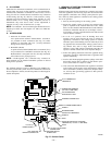
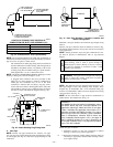
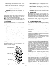
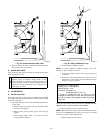
3. Install pipe support (factory-supplied in loose parts bag)
into selected furnace casing vent pipe hole. Pipe support
should be positioned at bottom of casing hole.
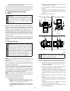
4. Be certain that mating surfaces of inducer housing connec-
tion, elastomeric coupling, and 2-in. diameter vent pipe are
clean and dry. Assemble the elastomeric (rubber) vent
coupling (with 2 loose clamps) onto inducer housing
connection. Insert the 2-in. diameter vent pipe through the
elastomeric (rubber) coupling and fully into inducer hous-
ing connection until it bottoms on the internal stop. Tighten
both clamps to secure the pipe to inducer housing. Tighten
the clamp screws to 15 in.-lb. of torque.
WARNING: Vent pipe must be installed and fully
seated against inducer housing internal stop. Clamp must
be tightened to prevent any condensate leakage. Failure to
follow this warning could result in electrical shock, fire,
personal injury, or death.
NOTE: A 2-in. diameter pipe must be used within the furnace
casing. Make all pipe diameter transitions outside furnace casing.
VENT EXTENSION PIPE
Some furnaces are supplied with a PVC vent extension pipe
(2-in. diameter by 12-in. long). This pipe has a built-in
channel to assist vent condensate disposal. When this vent
extension pipe is supplied, it must be used to connect the
field vent pipe to furnace inducer housing on ALL upflow
and downflow applications.
NOTE: See label on vent extension pipe for proper installation.
This pipe may be shortened if an elbow is used to connect vent
extension tube to field-installed vent pipe.
5. Working from furnace to outside, cut pipe to required
length(s).
6. Deburr inside and outside of pipe.
7. Chamfer outside edge of pipe for better distribution of
primer and cement.
8. Clean and dry all surfaces to be joined.
9. Check dry fit of pipe and mark insertion depth on pipe.
NOTE: It is recommended that all pipes be cut, prepared, and
preassembled before permanently cementing any joint.
10. After pipes have been cut and preassembled, apply gener-
ous layer of cement primer to pipe fitting socket and end of
pipe to insertion mark. Quickly apply approved cement to
end of pipe and fitting socket (over primer). Apply cement
in a light, uniform coat on inside of socket to prevent
buildup of excess cement. Apply second coat.
11. While cement is still wet, twist pipe into socket with 1/4
turn. Be sure pipe is fully inserted into fitting socket.
12. Wipe excess cement from joint. A continuous bead of
cement will be visible around perimeter of a properly made
joint.
13. Handle pipe joints carefully until cement sets.
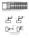
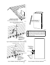
14. Support vent piping a minimum of every 5 ft (3 ft for
SDR-21 or -26 PVC) using perforated metal hanging strap.
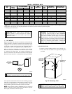
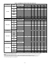
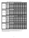
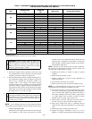
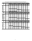
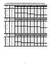
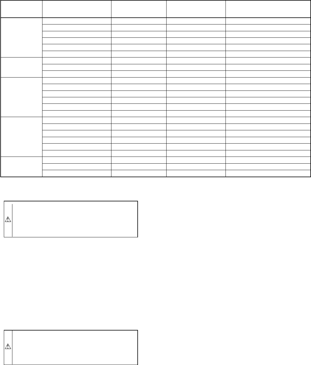
TABLE 5—MAXIMUM ALLOWABLE EXPOSED VENT PIPE LENGTH (FT) WITH INSULATION IN
WINTER DESIGN TEMPERATURE AMBIENT*
UNIT
SIZE
WINTER DESIGN
TEMPERATURE
(°F)
MAX PIPE
DIAMETER
(IN.)
WITHOUT
INSULATION
WITH 3/8-IN. OR
THICKER INSULATION†
040
20 1.5 51 70
0 1.5 28 70
-20 1.5 16 70
20 2 45 70
0 2 22 70
-20 2 10 58
060
20 2 65 70
0 2 35 70
-20 2 20 70
080
20 2 55 55
0 2 48 55
-20 2 30 55
20 2.5 70 70
0 2.5 47 70
-20 2.5 28 70
100
20 2.5 40 40
0 2.5 40 40
-20 2.5 38 40
20 3 70 70
0 3 50 70
-20 3 28 70
120
20 3 70 70
0 3 61 70
-20 3 37 70
* Pipe length (ft) specified for maximum pipe lengths located in unconditioned spaces. Pipes located in unconditioned space cannot exceed total allowable pipe length as
specified in Table 4.
† Insulation thickness based on R value of 3.5 (ft
2
•°F•hr.)/(Btu•in.)
—28—
→
→