


CAUTION: If a flexible connector is required or al-
lowed by authority having jurisdiction, black iron pipe
shall be installed at gas valve and extend a minimum of
2 in. outside furnace casing.
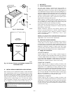
An accessible manual shutoff valve MUST be installed upstream
of furnace gas controls and within 6 ft of furnace. A 1/8-in. NPT
plugged tapping, accessible for test gage connection, MUST be
installed immediately upstream of gas supply connection to
furnace and downstream of manual shutoff valve.
NOTE: The gas valve inlet press tap connection is suitable to use
as test gage connection providing test pressure DOES NOT exceed
maximum 0.5 psig (14-in. wc) stated on gas valve. (See Fig. 40.)
Piping should be pressure tested in accordance with local and
national plumbing and gas codes before furnace is attached. In
Canada, refer to current edition of NSCNGPIC. If pressure
exceeds 0.5 psig (14-in. wc), gas supply pipe must be disconnected
from furnace and capped before pressure test. If test pressure is
equal to or less than 0.5 psig (14-in. wc), turn off electric shutoff
switch located on gas valve before test. It is recommended that
ground joint union be loosened before pressure testing. After all
connections have been made, purge lines and check for leakage.
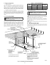
ELECTRICAL CONNECTIONS
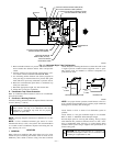
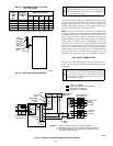
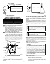
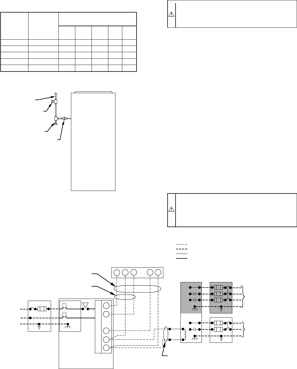
See Fig. 24 for field wiring diagram showing typical field 115-v
and 24-v wiring. Check all factory and field electrical connections
for tightness.
WARNING: Blower access panel door switch opens
115-v power to control center. No component operation
can occur. Do not bypass or close switch with panel
removed. Failure to follow this warning could result in
personal injury or death.
Fig. 24—Heating and Cooling Application Wiring Diagram
A98209
115-V
FIELD-SUPPLIED
DISCONNECT
AUXILIARY
J-BOX
CONTROL
BOX
24-V
TERMINAL
BLOCK
THREE-WIRE
HEATING-
ONLY
FIVE
WIRE
NOTE 1
NOTE 2
FIELD-SUPPLIED
DISCONNECT
CONDENSING
UNIT
TWO
WIRE
FURNACE
R
G
C
WCR GY
GND
GND
FIELD 24-V WIRING
FIELD 115-, 208/230-, 460-V WIRING
FACTORY 24-V WIRING
FACTORY 115-V WIRING
208/230- OR
460-V
THREE
PHASE
208/230-V
SINGLE
PHASE
WHT
BLK
WHT
BLK
NOTES: Connect Y-terminal as shown for proper operation.
Some thermostats require a "C" terminal connection as shown.
If any of the original wire, as supplied, must be replaced, use
same type or equivalent wire.
W
Y
GND
THERMOSTAT
TERMINALS
1.
2.
3.
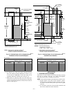
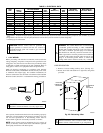
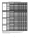
TABLE 2—MAXIMUM CAPACITY OF PIPE
(CU FT PER HR)*
NOMINAL
IRON
PIPE
SIZE
(IN.)
INTERNAL
DIAMETER
(IN.)
LENGTH OF PIPE (FT)
10 20 30 40 50
1/2 0.622 175 120 97 82 73
3/4 0.824 360 250 200 170 151
1 1.049 680 465 375 320 285
1-1/4 1.380 1400 950 770 660 580
1-1/2 1.610 2100 1460 1180 990 900
* For gas pressures of 0.5 psig (14-in. wc) or less, and a pressure drop of
0.5-in. wc (based on a 0.60 specific gravity gas). Ref: Table 10-2 NFGC .
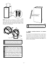
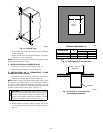
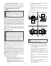
Fig. 23—Typical Gas Pipe Arrangement
A93324
UNION
SEDIMENT
TRAP
MANUAL
SHUTOFF
VALVE
(REQUIRED)
GAS
SUPPLY
—19—