


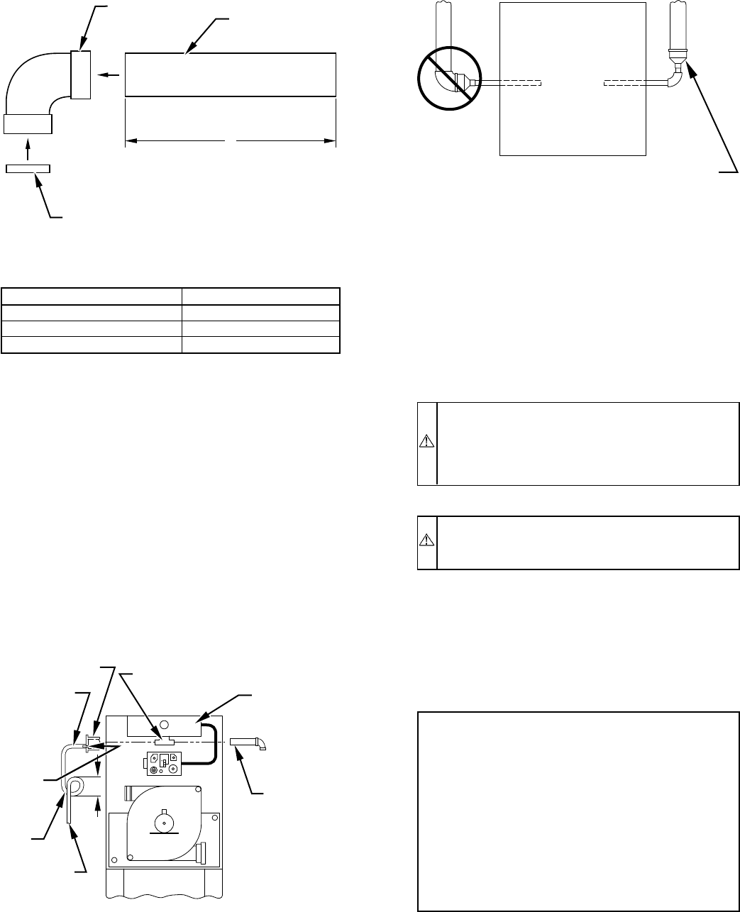
NOTE: Do not attach combustion-air intake pipe permanently to
combustion-air intake housing since it may be necessary to remove
pipe for service of ignitor or flame sensor.
The combustion-air intake plug fitting must be installed in
unused combustion-air intake housing. This fitting must be
attached by using RTV sealant, or by drilling a 1/8-in. hole
in fitting, using hole in intake housing as a guide. Install a
field-supplied No. 6 or No. 8 sheet metal screw.
NOTE: DO NOT OVERTIGHTEN SCREW. Breakage to intake
housing or fitting may cause air leakage to occur.
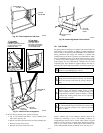
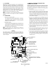
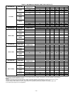
A plugged drain connection has been provided on this
fitting for use when moisture is found in combustion-air
intake pipe and combustion box. If use of this drain
connection is desired, drill out fitting’s tap plug with a
3/16-in. drill and connect a field-supplied 3/8-in. tube. This
tube should be routed to open condensate drain for furnace
and A/C (if used), and should be trapped. (See Fig. 30.)
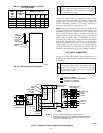
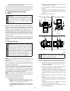
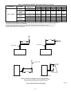
C. Vent Pipe
NOTE: Furnace vent pipe connections are sized for 2-in. pipe.
Any vent pipe size change should be made outside furnace casing
in vertical pipe. (See Fig. 31.) This allows proper drainage of vent
condensate.
Determine vent pipe diameter and maximum pipe lengths using
Table 4.
Furnace vent pipe connection must be attached as shown in Fig.
28. Inducer housing alternate vent cap may need to be relocated in
some applications.
NOTE: Starting at furnace, slope vent pipe a minimum of 1/4 in.
per linear ft upward to termination(s) with no sags between
hangers.
CAUTION: When vent pipe is exposed to temperatures
below freezing, such as when it passes through an
unheated space or when a chimney is used as a raceway,
pipe must be insulated as described in Table 5 with
Armaflex-type insulation.
WARNING: Vent pipes must be airtight and watertight.
Failure to follow this warning could result in property
damage, personal injury, or death.
NOTE: The minimum vent pipe length for these furnaces is 5 ft.
Short pipe lengths (5-8 ft) may discharge water droplets. These
droplets may be undesirable, and a 12-in. minimum offset pipe
section is recommended to reduce excessive droplets from exiting
vent pipe outlet. (See Fig. 32.)
NOTE: Do not count elbows or pipe sections in terminations or
within furnace. See shaded areas in Fig. 34.
EXAMPLE:
An 036080 size furnace located in Indianapolis, eleva-
tion 650 ft above sea level, could be installed in an
application requiring 3 elbows and 32 ft of vent pipe.
Table 4 indicates this application would allow a 2-in.
diameter vent pipe. At 0-2000 ft elevation, 2-in. pipe is
good for up to 35 ft with 3 elbows. If same installation
were in Albuquerque, elevation 5250 ft above sea
level, installation would require 2-1/2 in. vent pipe. At
5001- to 6000-ft elevation, 2-in. pipe is allowed for up
to 23 ft with 3 elbows, but 2-1/2 in. pipe can be used for
up to 70 ft with 3 elbows.
Install vent pipe as follows:
1. Determine location of vent pipe connection to inducer
housing as shown in Fig. 28 for application.
2. Reposition elastomeric (rubber) inducer housing outlet cap
and clamp to appropriate unused inducer housing connec-
tion. Tighten clamp.
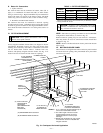
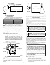
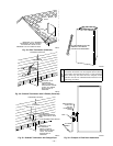
Fig. 29—Combustion-Air Inlet Pipe Assembly
LENGTH OF STRAIGHT PIPE PORTION OF
COMBUSTION-AIR INLET PIPE ASSEMBLY (IN.)
CASING WIDTH A
17-1/2 8-1/2 ± 1/2
21 10-1/2 ± 1/2
24-1/2 12 ± 1/2
A96211
FIELD-SUPPLIED
2-IN. DIAMETER
PVC PIPE
FIELD-SUPPLIED
2-IN. DIAMETER
PVC 90° ELBOW
COMBUSTION-AIR DISC
(FACTORY-SUPPLIED IN
LOOSE PARTS BAG)
A
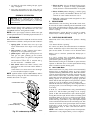
Fig. 30—Intake Housing Plug Fitting Drain
A96190
COMBUSTION–
AIR PIPE
BURNER
BOX
COMBUSTION–AIR
INTAKE HOUSING
3/8
″ ID TUBE
TRAP
TO OPEN
DRAIN
3/16
″
DRILL
HOUSING
PLUG
4″
MIN
Fig. 31—Vent Pipe Diameter Transition Location and
Elbow Configuration
A93034
FURNACE
PIPE DIAMETER
TRANSITION IN
VERTICAL SECTION
NOT IN
HORIZONTAL
SECTION
—24—
→