


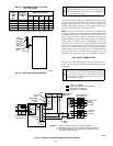
II. 24-V WIRING
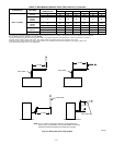
Make field 24-v thermostat connections at 24-v terminal block on
control center. For proper cooling operation, Y wire from thermo-
stat MUST be connected to Y terminal on control center, as shown
in Fig. 24. The 24-v terminal board is marked for easy connection
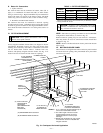
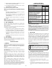
of field wiring. (See Fig. 26.) The 24-v circuit contains a 3-amp,
automotive-type fuse located on control center. (See Fig. 27.) Any
electrical shorts of 24-v wiring during installation, service, or
maintenance may cause fuse to blow. If fuse replacement is
required, use only a fuse of identical size (3 amp).
NOTE: Use AWG No. 18 color-coded copper thermostat wire for
lengths up to 100 ft. For wire lengths over 100 ft, use AWG No.
16 wire.
III. ACCESSORIES
1. Electronic Air Cleaner (EAC)
Two quick-connect terminals marked EAC-1 and EAC-2
are provided for EAC connection. (See Fig. 27.) These
terminals are energized with 115v (1.5-amp maximum)
during blower motor operation.
2. Humidifier (HUM)
A quick-connect terminal (HUM) and screw terminal (C
OM)
are provided for 24-v humidifier connection. (See Fig. 26.)
HUM terminal is energized with 24v (0.5-amp maximum)
after inducer motor prepurge period.
NOTE: A field-supplied, 115-v controlled relay connected to
EAC terminals may be added if humidifier operation is desired
during blower operation.
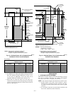
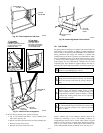
VENTING
The 345MAV Furnaces require a dedicated, (one 345MAV fur-
nace only) sealed vent system. All air for combustion is taken from
the area adjacent to furnace, and all flue products are discharged to
outside atmosphere.
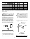
I. REMOVAL OF EXISTING FURNACES FROM
COMMON VENT SYSTEMS
If furnace being replaced was connected to a common vent system
with other appliances, the following steps shall be followed with
each appliance connected to the venting system placed in opera-
tion, while any other appliances connected to the venting system
are not in operation:
1. Seal any unused openings in the venting system.
2. Inspect the venting system for proper size and horizontal
pitch as required in the National Fuel Gas Code, ANSI
Z223.1 or the CAN/CGA B149 Installation Codes and these
instructions. Determine that there is no blockage or restric-
tion, leakage, corrosion, and other deficiencies which could
cause an unsafe condition.
3. In so far as is practical, close all building doors and
windows and all doors between the space in which the
appliance(s) connected to the venting system are located
and other spaces of the building. Turn on clothes dryers and
any appliance not connected to the venting system. Turn on
any exhaust fans, such as range hoods and bathroom
exhausts, so they shall operate at maximum speed. Do not
operate a summer exhaust fan. Close fireplace dampers.
4. Follow the lighting instructions. Place the appliance being
inspected in operation. Adjust thermostat so appliance shall
operate continuously.
5. Test for draft hood equipped appliance spillage at the draft
hood relief opening after 5 minutes of main burner opera-
tion. Use the flame of a match or candle.
6. After it has been determined that each appliance connected
to the venting system properly vents when tested as outlined
above, return doors, windows, exhaust fans, fireplace damp-
ers, and any other gas-burning appliance to their previous
conditions of use.
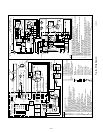
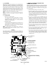
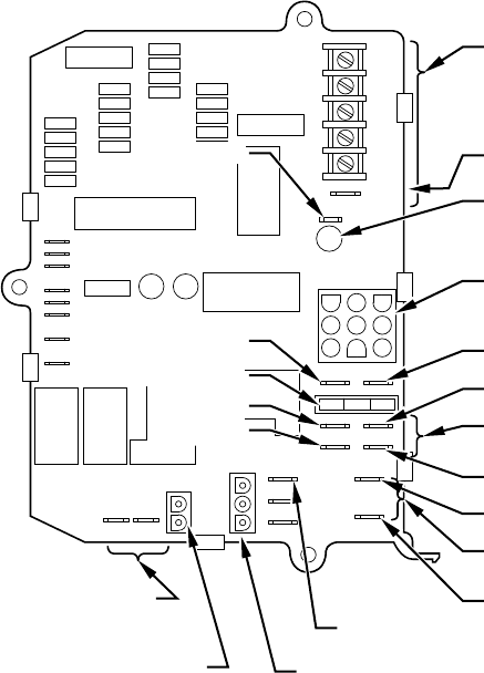
Fig. 27—Control Center
A95086
C
OM
24V
HUM
GRYW
3-AMP FUSE
HUMIDIFIER TERMINAL
(24-VAC 0.5 AMP MAX)
LED OPERATION &
DIAGNOSTIC LIGHT
HARNESS CONNECTOR
24-V TRANSFORMER SEC-2
SPARE-1
SPARE-2
EAC-1
EAC-ELECTRONIC AIR CLEANER
TERMINALS (115-VAC 1.5 AMP MAX)
EAC-2
115-VAC (L2) NEUTRAL
CONNECTION
24-V THERMOSTAT
TERMINALS
BLOWER SPEED
SELECTION TERMINALS
INDUCER MOTOR
CONNECTOR
115-VAC (L1)
POWER SUPPLY
HOT SURFACE
IGNITOR CONNECTOR
HEAT
COOL
SEC-1
TEST/TWIN
—22—