


7. If improper venting is observed during any of above tests,
the venting system must be corrected.
Vent system or vent connectors may need to be resized. For any
other appliances when resizing vent systems or vent connectors,
system or connector must be sized to approach minimum size
determined in appropriate table in NFGC or NSCNGPIC.
II. COMBUSTION-AIR AND VENT PIPING
A. General
WARNING: Solvent cements are combustible. Keep
away from heat, sparks, and open flame. Use only in
well-ventilated areas. Avoid breathing in vapor or allow-
ing contact with skin or eyes. Failure to follow this
warning could result in fire, property damage, personal
injury, or death.
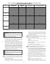
Combustion-air and vent pipe fittings must conform to American
National Standards Institute (ANSI) standards and American
Society for Testing and Materials (ASTM) standards D1785
(schedule-40 PVC), D2665 (PVC-DWV), D2241 (SDR-21 and
SDR-26 PVC), D2661 (ABS-DWV), F628 (schedule-40 ABS), or
F891 (PVC-DWV cellular core) or F441 schedule-40 CPVC pipe)
and F438 (schedule-40 CPVC fittings). Pipe cement and primer
must conform to ASTM standards D2564 or F493 (PVC or CPVC)
or D2235 (ABS).
In Canada construct all combustion-air and vent pipes for this unit
of CSA or ULC certified schedule-40 PVC, PVC-DWV or
ABS-DWV pipe and pipe cement. SDR pipe is NOT approved in
Canada.
B. Combustion Air Pipe
CAUTION: Combustion air must not be taken from
inside a structure that is frequently contaminated by
halogens, which include fluorides, chlorides, bromides,
and iodides. These elements are found in aerosols,
detergents, bleaches, cleaning solvents, salts, air freshen-
ers, adhesives, paint, and other household products.
Locate combustion-air inlet as far as possible from
swimming pool and swimming pool pump house.
Excessive exposure to contaminated combustion air will
result in safety and performance related problems.
NOTE: Furnace combustion-air connections are sized for 2-in.
pipe. The combustion-air pipe will be 2-in. diameter in all
installations.
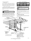
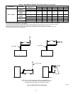
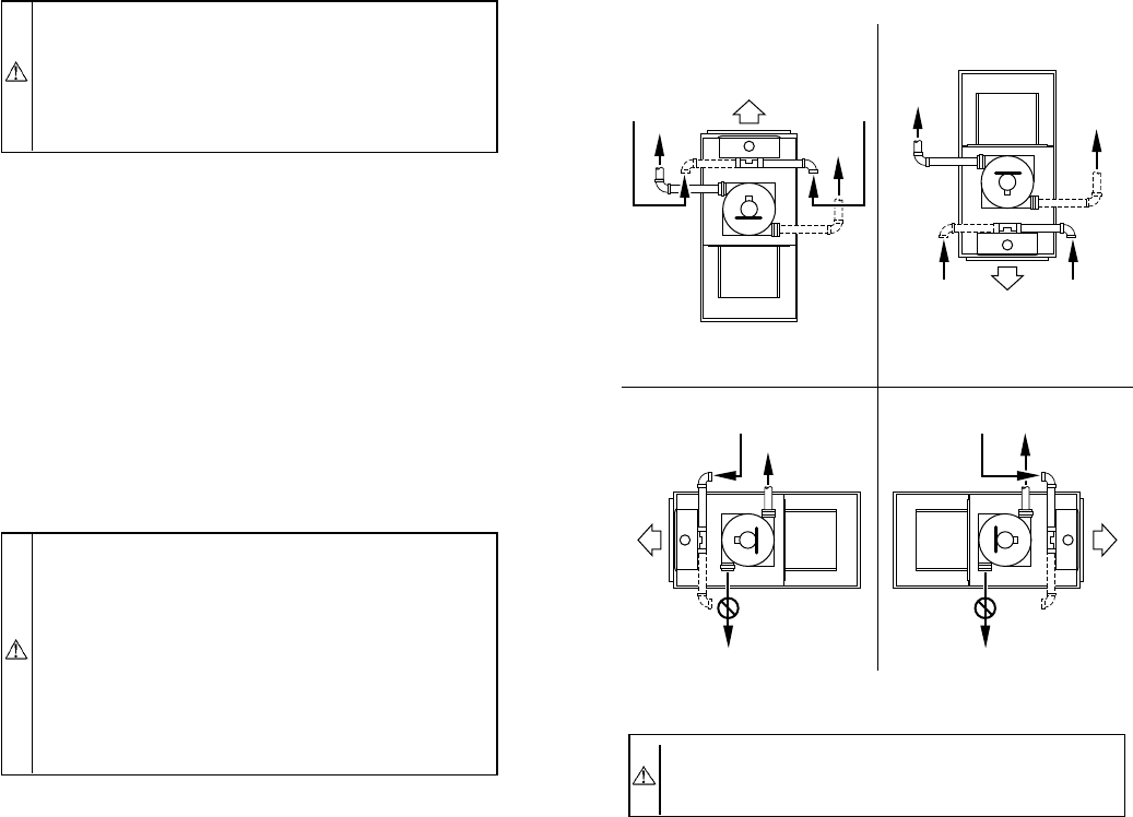
Furnace combustion-air connection must be attached as shown in
Fig. 28. Combustion-air intake housing plug may need to be
relocated in some applications.
Combustion-air pipe must terminate outside of furnace casing with
1 elbow. Orient elbow so that opening faces down for upflow or
downflow applications. Orient elbow so that it faces sideways (left
or right) for horizontal left or horizontal right applications. (See
Fig. 28.) Maintain a 3-in. minimum clearance between the opening
of the combustion-air inlet pipe and any object.
NOTE: All pipe joints must be watertight except attachment of
combustion-air inlet pipe to inlet housing connection, since it may
be necessary to remove pipe for servicing.
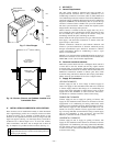
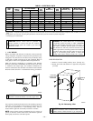
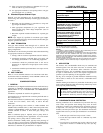
Install combustion air inlet pipe as follows:
1. Assemble combustion-air inlet pipe.
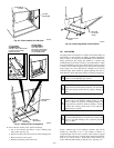
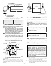
a. Permanently install perforated disk assembly (factory-
supplied in loose parts bag) in combustion-air elbow
using RTV or by cementing. (See Fig. 29.)
For 120,000 Btuh size units only: Separate the 2 halves
of perforated disk assembly and use only the shouldered
disk half.
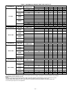
b. Determine length of straight portion of combustion-air
inlet pipe from table in Fig. 29.
c. Cut field-supplied 2-in diameter PVC pipe to determined
length.
d. Permanently attach elbow/perforated disk assembly to
straight portion of pipe using RTV or by cementing. (See
Fig. 29.)
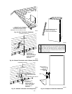
2. Attach combustion-air inlet pipe.
a. Determine location of combustion-air intake pipe con-
nection to combustion-air intake housing as shown in
Fig. 28 for application.
b. Reposition combustion-air intake housing plug fitting in
appropriate unused intake housing connection.
c. Install pipe support (factory-supplied in loose parts bag)
into selected furnace casing combustion-air pipe hole.
Pipe support should be positioned at bottom of casing
hole.
d. Insert assembled combustion-air inlet pipe into intake
housing.
e. Make sure elbow is oriented in an acceptable direction
and that the minimum clearance of 3 in. is observed. (See
Fig. 28.)
f. Drill a 1/8-in. hole in 2-in. combustion-air inlet pipe
using hole in intake housing as a guide.
g. Install a field-supplied No. 6 or No. 8 sheet metal screw
into combustion-air pipe.
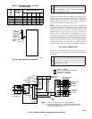
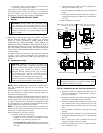
Fig. 28—Combustion-Air and Vent Pipe Connections
CAUTION: Make sure there is adequate clearance (3-in.
minimum) to any fixed or loose objects in order to ensure
an adequate combustion-air supply.
A96188
COMBUSTION-
AIR
COMBUSTION-
AIR
AIR
FLOW
VENT
VENT
VENT
AIR
FLOW
AIR
FLOW
AIR
FLOW
UPFLOW DOWNFLOW
HORIZONTAL-LEFT DISCHARGE HORIZONTAL-RIGHT DISCHARGE
Select 1 vent pipe connection and
1 combustion-air pipe connection.
COMBUSTION-
AIR
COMBUSTION-
AIR
COMBUSTION-
AIR
COMBUSTION-
AIR
NOTE: Select 1 vent pipe connection and
1 combustion-air pipe connection.
NOTE:
VENT
VENT
VENT
—23—
→