


15. Slope vent pipe toward furnace a minimum of 1/4 in. per
linear ft with no sags between hangers.
16. Use appropriate methods to seal openings where vent pipe
passes through roof or sidewall.
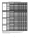
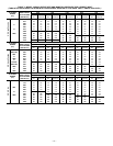
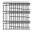
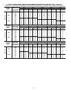
D. Extended Exposed Sidewall Pipes
Sidewall vent pipe termination may be extended beyond area
shown in Fig. 34 in outside ambient by insulating pipe as indicated
in Table 5.
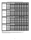
1. Determine vent pipe diameter, as stated above, using total
pipe length and number of elbows.
2. Find appropriate temperature for your application and
furnace model using winter design temperature (used in
load calculations).
3. Determine required insulation thickness for exposed pipe
lengths.
NOTE: Pipe length (ft) specified for maximum pipe lengths
located in unconditioned spaces cannot exceed total allowable pipe
length as specified in Table 4.
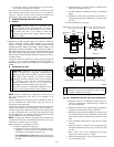
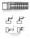
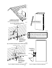
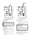
III. VENT TERMINATION
Vent pipe must terminate either through roof or sidewall. See
Table 6 for required clearances. See Fig. 33, 34, and 35 for exterior
piping arrangements.
Consideration of the following should be made when determining
an appropriate location for termination:
1. Comply with all clearance requirements stated in Table 6.
2. Termination should be positioned where vent vapors will
not damage plants/shrubs or air conditioning equipment.
3. Termination should be positioned where it will not be
damaged by or subjected to foreign objects such as stones,
balls, etc.
4. Termination should be positioned where vent vapors are not
objectionable.
IV. MULTIVENTING
When 2 or more 345MAV Furnaces are vented near each other,
each furnace must be individually vented. NEVER common vent
or breach vent 345MAV furnaces.
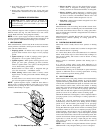
CONDENSATE DRAIN
I. GENERAL
Condensate trap is shipped installed in the blower shelf and factory
connected for UPFLOW applications. Condensate trap must be
RELOCATED for use in DOWNFLOW and HORIZONTAL
applications.
Condensate trap MUST be used for all applications.
An external trap is not required when connecting the field drain to
this condensate trap.
The field drain connection (condensate trap or drain tube coupling)
is sized for 1/2-in. CPVC, 1/2-in. PVC, or 5/8-in. ID tube
connection.
Drain pipe and fittings must conform to ANSI standards and
ASTM D1785 or D2846. CPVC or PVC cement and primer must
conform to ASTM D2564 or F493. In Canada, use CSA or ULC
certified schedule 40 CPVC or PVC drain pipe, fittings, and
cement.
When a condensate pump is required, select a pump which is
approved for condensing furnace applications. To avoid conden-
sate spillage, select a pump with an overflow switch.
Furnace condensate is mildly acidic, typically in the pH range of
3.2 to 4.5. Due to corrosive nature of unneutralized condensate, a
condensate pH neutralizing filter may be desired. Check with local
authorities to determine if a pH neutralizer is required.
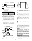
II. APPLICATION
The furnace, A/C, and humidifier drains may be combined and
drained together. The A/C drain must have an external, field-
supplied trap prior to the furnace drain connection. All drain
connections (furnace, A/C, or humidifier) must be terminated into
an open or vented drain as close to the respective equipment as
possible to prevent siphoning of the equipment’s drain.
See Fig. 36 for example of possible field drain attachment using
1/2-in. CPVC or PVC tee for vent and A/C or humidifier drain
connection.
Outdoor draining of the furnace is permissible if allowed by local
codes. Caution should be taken when freezing ambient may freeze
drain pipe and prohibit draining.
WARNING: Caution should be taken to prevent drain-
ing where slippery conditions may cause personal inju-
ries. Excessive condensate draining may cause saturated
soil conditions which may result in damage to plants.
III. CONDENSATE DRAIN PROTECTION
Freezing condensate left in condensate trap and drain line may
cause cracks, and possible water damage may occur. If freeze
protection is required, use condensate freeze protection accessory
or equivalent 3 to 6 watt per ft at 120v and 40°F self-regulating,
shielded, and waterproof heat tape. See Installation Instructions
supplied with accessory or heat tape manufacturer’s recommenda-
tions.
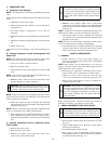
1. Fold heat tape in half and wrap on itself 3 times.
2. Locate heat tape between sides of condensate trap back.
(See Fig. 37.)
3. Use wire ties to secure heat tape in place. Wire ties can be
positioned in notches of condensate trap sides. (See Fig.
37.)
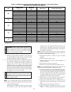
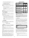
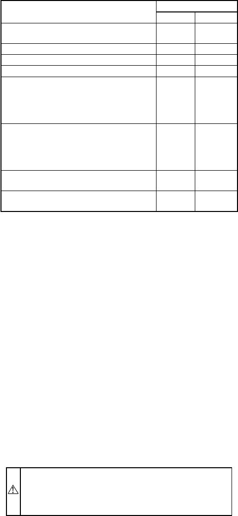
TABLE 6—VENT PIPE
TERMINATION CLEARANCES
LOCATION
CLEARANCE (FT)
U.S.A. Canada
Above grade level or above antici-
pated snow depth
11†
Dryer vent 33
From plumbing vent stack 33
From any mechanical fresh air intake 16
For furnaces with an input capacity of
100,000 Btuh or less—from any non-
mechanical air supply (windows or
doors which can be opened) or
combustion-air opening
11
For furnaces with an input capacity
greater than 100,000 Btuh—from any
non-mechanical air supply (windows
or doors which can be opened) or
combustion-air opening
13
From service regulator vent, electric
and gas meters, and relief equipment
4* 6‡
Above grade when adjacent to public
walkway
Note 3 Note 3
* Horizontal distance.
† 18 in. above roof surface in Canada.
‡ 36 in. to electric meter in Canada only.
NOTES:
1. If installing 2 adjacent 345MAV Furnaces, refer to Multiventing and Vent
Terminations section for proper vent configurations.
2. When locating vent terminations, consideration must be given to prevailing
winds, location, and other conditions which may cause recirculation of the
appliance’s own flue products or the flue products of adjacent vents. Recircu-
lation can causepoor combustion,inlet condensateproblems, and accelerated
corrosion of heat exchangers.
3. Vent termination can not terminate less than 2 ft horizontal and 7 ft above
public walkway or where condensate vapor or droplets may be a hazard.
—29—