


2000 Series | Program Entry Guide | 13.0 Relays EN | 53
Bosch Security Systems | 7/05 | 35114F
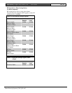
13.0 Relays
A D133 or D134 Relay Module is required to use the
system’s external relay outputs (Terminals 9 and 10).
One module is required for each output used. Refer to
the Installation Manual for instructions.
You can program each of the system’s two relay
outputs with one or two functions. With the
Relay #
Logic
prompts, you can configure the outputs so they
activate when the condition for either function exists,
or only activate when the conditions for both functions
exist.
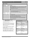
The D5200 Programmer displays an additional relay
parameter prompt if the Relay function you selected
requires you to program additional information.
For example, if you select the Follow Point function
for
Relay 1, Func 1
and press [Enter], the D5200
displays the parameter prompts,
Point 1
(Yes, No),
followed by
Point 2
(Yes, No), and so on until
Point
24
(Yes, No). The parameter prompts tell the system
what points the relay is to follow.
If you select Reset for
Relay 1, Func 1
and press
[Enter], the D5200 goes directly to
Relay 1, Func 2
.
The Reset function does not require any parameters.
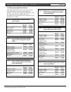
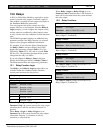
13.1 Relay Function Logic
The
Relay 1
, and
Relay 2, Logic
prompts allow you
to further define the conditions under which the
control panel activates the relay drivers.
1 Relay 1 Logic
2 Relay 2 Logic
Default:
Function 1 Only
Selection:
Function 1 Only
Function 1 or 2
Function 1 and 2
0 Function 1 Only
1 Function 1 or 2
2 Function 1 and 2
When
Relay 1 Logic
or
Relay 2 Logic
is set to
Function 1 Only, the system activates the relay output
when Function 1 calls for activation. Function 2 is
ignored.
When
Relay 1 Logic
or
Relay 2 Logic
is set to
Function 1 or 2, the system activates the relay output
when either Function 1 or Function 2 calls for
activation, or when both do.
When
Relay 1 Logic
or
Relay 2 Logic
is set to
Function 1 and 2, both Function 1 and Function 2
must call for activation before the system activates
the relay output.
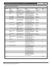
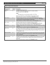
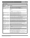
13.2 Relay Functions
3 Relay 1 Func 1
Default:
No Output
Selection:
Refer to Table 18 (0 to 24)
The
Relay 1, Func 1
prompt sets Function 1 for
Relay Output 1 (Terminal 9).
4 Relay 1 Func 2
Default:
No Output
Selection:
Refer to Table 18 (0 to 24)
The
Relay 1, Func 2
prompt sets Function 2 for
Relay Output 1 (Terminal 9).
5 Relay 2 Func 1
Default:
No Output
Selection:
Refer to Table 18 (0 to 24)
The
Relay 2, Func 1
prompt sets Function 1 for
Relay Output 2 (Terminal 10).
6 Relay 2 Func 2
Default:
No Output
Selection:
Refer to Table 18 (0 to 24)
The
Relay 2, Func 6
prompt sets Function 6 for
Relay Output 2 (Terminal 10)