


2000 Series | Program Entry Guide | 11.0 Point Codes EN | 35
Bosch Security Systems | 7/05 | 35114F
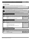
11.0 Point Codes
Use the point code charts to set a five-digit point code for each point. The point code determines how the
system responds to changes on the point sensor loops. Points respond to opens and shorts.
RF expansion points respond with short for faulted devices.
When an RF point trips, another trip of the same sensor is not detected for 5 or more seconds, depending upon
sensor type. Refer to the Installation Manual for a complete description of point sensor loops.
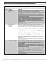
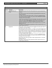
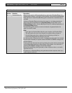
0101
0101
0101
First three digits for E version control panels: E version control panels (for example, D2412UE) only
include the On-board points. Point Code Digits 4 and 5 tell the control panel where Off-board points are
located. E version control panels ignores Point Code Digits 4 and 5.
The tables on the pages that follow show the defaults and selections for programming.
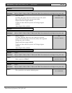
1 Point 1
Default:
2600A
Selection:
Refer to Table 5, Table 6, Table 7, Table 8, and Table 9 for selections for each digit in the point code.
2600A
Fire point
Fire point with alarm verification. Reports and alarm output
enabled.
Point 1 is powered for two-wire smoke detectors
PT1
FIRE/VERIFY
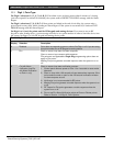
2 Point 2
Default:
8820A
Selection:
Refer to Table 5, Table 6, Table 7, Table 8, and Table 9 for selections for each digit in the point code.
8820A
Delay Door
Delayed Part point. Point arms when user turns the system Part
(or All) On. Point starts entry delay.
Reports and alarm output enabled.
Trouble on short when the system is off. Swinger bypass
enabled.
Alarm Report delay enabled.
PT2
PART/DELAY
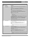
3 Point 3
Default:
8820A
Selection:
Refer to Table 5, Table 6, Table 7, Table 8, and Table 9 for selections for each digit in the point code.
8820A
Delay Door
Same response as
Point 2
.
PT3
PART/DELAY