56 Remote Programming
Writing to the Display
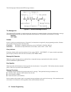
You can include messages to the front panel LCD in your programs. The description of DISP:TEXT in chapter 7 shows the
number and types of permitted display characters. In order to write to the display, you must first change it to text mode as
shown in the following example:
DIS:MODE TEXT Switch display to text mode.
RECALLED 2 Write “Recalled 2” to the display.
DIS:MODE NORM Return display to its normal mode.
Programming Status
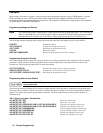
You can use status programming to make your program react to events within the Agilent SAS. Chapter 8 - Status
Reporting explains the functions and bit configurations of all status registers. Refer to figure 8-1 in that chapter while
examining the examples given here. Usually you will want the Agilent SAS to generate interrupts (assert SRQ) upon
particular events. For this you must selectively enable the appropriate status register bits. The following examples allow
the unit to assert SRQ under selected conditions.
STAT:OPER:ENAB 1280;PTR 1280;*SRE 128 Assert SRQ when the unit switches between CV and CC modes.
STAT:OPER:ENAB 1;PTR 1;NTR 1;*SRE 128 Assert SRQ when the unit enters or leaves calibration mode.
STAT:QUES 3;PTR 3;*SRE 128 Assert SRQ when the unit goes into overvoltage or overcurrent.
STAT:OPER:ENAB 1280;PTR 1280;
:STAT:QUES 3;PTR 3;*SRE 136
Assert SRQ under any event occurring in the operation or
questionable registers.
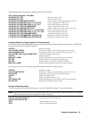
The following example illustrates how you can exercise program control without interrupts by reading specific registers.
STAT:OPER:1280;EVEN? Enable only the CV and CC events and read their status.
STAT:OPER:ENAB 1313;PTR 1313;EVEN? Enable all conditions of the Operation Status register and read any events.
STAT:OPER:ENAB?;EVENT?;
:STAT:QUES:ENAB?;EVEN?;:*ESE?;*ESR?
Read which events are active and which events are enabled in the
Operation, Questionable, and Standard Event status registers.
Note The last query string can be handled without difficulty. However, should you request too many queries, the system
may return a "Query DEADLOCKED” error (-430). In that case, break the long string into smaller parts.
Programming the Digital I/O Port
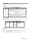
Digital control ports 1 and 2 are TTL outputs that can be programmed either high or low. Control port 3 can be
programmed to be either a TTL input or a TTL output. Send a decimal parameter that translates into the desired straight
binary code for these ports. (See DIG:DATA[:VAL] in chapter 7 for the port bit configurations.)
DIG:DATA 3 Set ports 1 and 2 high and make 3 another output port.
DIG:DATA 7 Set ports 1 and 2 high and make 3 an input port.
DIG:DATA? Read back the present port configuration.
System Considerations
The remainder of this chapter addresses some system issues concerning programming. These are addressing and the use of
the following types of GPIB system interfaces:
1. HP Vectra PC controller with Agilent 82335A GPIB Interface Command Library.
2. IBM PC controller with National Instruments GPIB-PCII Interface/Handler.
3. Agilent controller with Agilent BASIC Language System.
The example program at the end of this chapter is intended to show how some of the same Agilent SAS functions can be
programmed for the Agilent BASIC interface.


