


User Connections 37
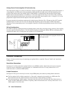
3. Remove or disable the Agilent SAS OVP crowbar SCR. For further information, contact an Agilent Service Engineer
through your local Agilent Sales and Support Office.
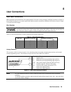
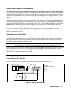
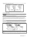
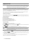
Figure 4-9. Using Series Diodes with Auto-Parallel Operation
Connecting Supplies in Series
Only connect units in series that have identical voltage and current ratings. Floating voltages must
not exceed
±
240 Vdc. No output terminal may be more than 240V from chassis ground. When operating
in Simulator mode, units must be programmed with identical curves. When operating in Table mode,
units must be programmed with identical table data.
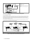
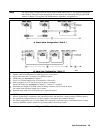
Figure 4-10 shows how Agilent SAS units can be connected in series for higher voltage output. Series connections are
straightforward in this case. Program each Agilent SAS independently. In Fixed mode, program each unit for 50% of the
total output voltage. Set the current limit of each unit to the maximum that the load can handle without damage. In
Simulator mode, the total Voc that will be provided is the sum of the open circuit voltages programmed for each individual
unit.
Each Agilent SAS has a reverse voltage protection diode across its output. If a reverse voltage is
applied, the unit cannot control the current conducted through this diode. To avoid damaging the unit,
never connect it in such a way that a reverse voltage can force it to conduct current in excess of the
unit’s output current rating.
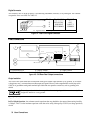
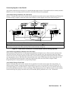
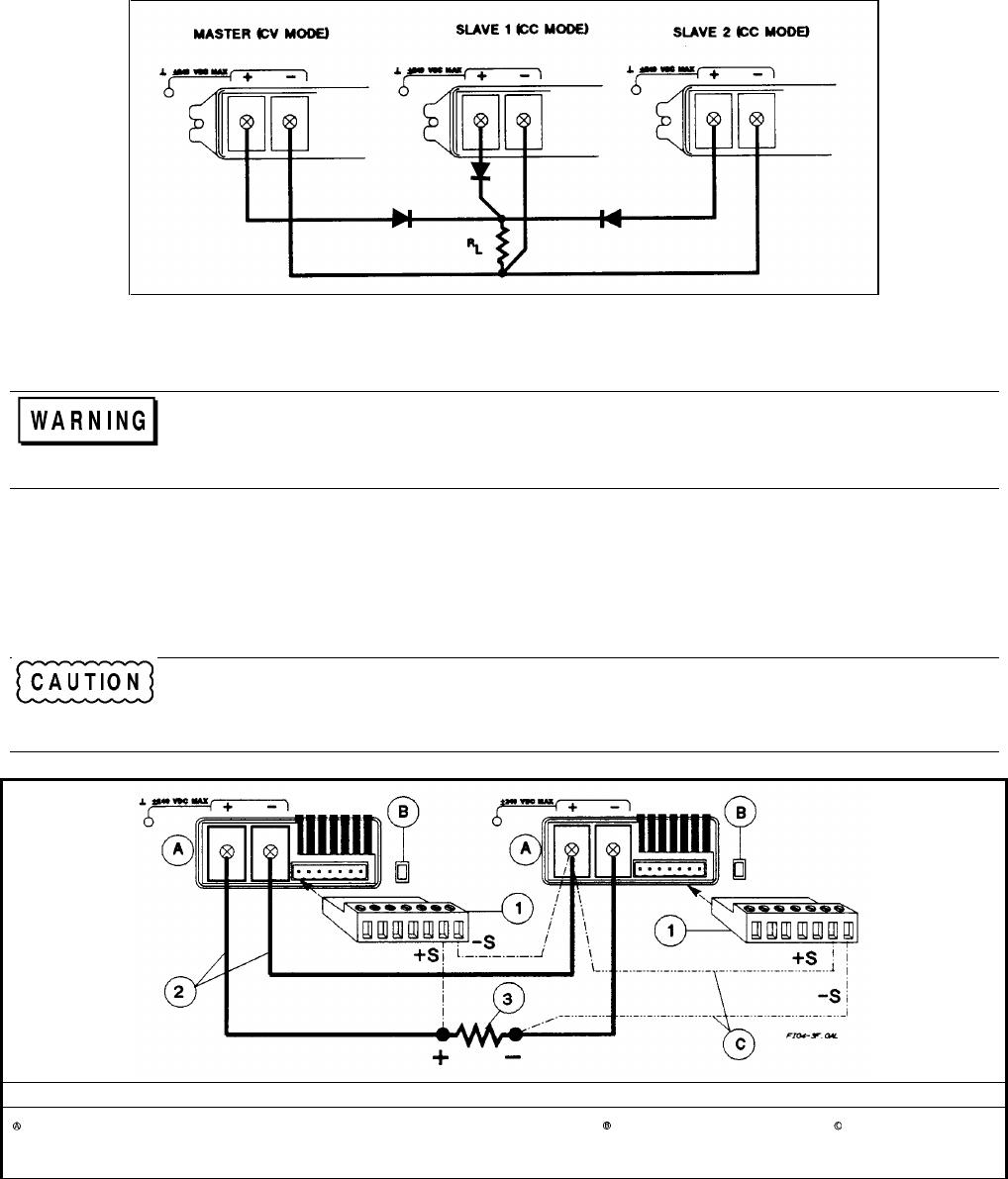
Analog Connector ôLoad Connection íLoad
In Fixed mode, program each unit for 1/2 the load voltage. In SAS
mode, the total Voc is the sum of the individual open circuit voltages of
each unit.
Set switch for local or
(optional) remote sensing
Optional remote
sense connections
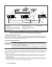
Figure 4-10. Series Connection (Remote Sensing Optional)