


User Connections 31
Because of its high output voltage, the Agilent E4351B generates high currents when discharging the
load capacitor under overvoltage conditions. Excessive currents can damage the unit. The peak
discharge current is limited by the sum of the external capacitor’s ESR (equivalent series resistance)
and the series resistance of the external circuit. For the Agilent E4351B’s external capacitance limit of
2,000
µ
F, the total resistance must not be less than 56 milliohms. For smaller values of external
capacitance, the total resistance may be derated linearly.
Inductive Loads
When operating in Simulator mode, load inductance should be kept under 200
µ
H. For twisted pair wires or zipcord, figure
approximately 0.25
µ
H per foot of load lead wire.
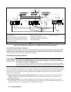
Connecting to an External Voltage Source
The Agilent SAS’s overvoltage circuit contains a crowbar SCR that effectively shorts the output of the unit whenever OVP
trips.
Note If the OVP trips, you must remove any external source of current in order to reset the internal SCR as part
of clearing the OVP circuit (see Clearing the OV Condition in chapter 8).
If an external voltage source such as a battery is connected across the output and the OVP is inadvertently triggered, the
Agilent SAS will continuously sink a large current from the source. This could damage the Agilent SAS. To avoid this,
insert a reverse blocking diode in series with either output of the Agilent SAS in the direction of normal output current flow.
The diode’s voltage rating should be at least 150% of the HP SAS’s output voltage rating. The diode may also require a
heat sink.
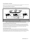
Sense Connections
Your Agilent SAS was shipped set up for local sensing. This means that the unit will sense and regulate its output voltage at
the output terminals, with the load voltage being somewhat lower due to load lead voltage drop. Where load voltage
regulation is critical, remote sensing may be required.
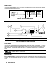
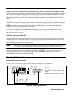
Local sensing is obtained by placing the SENSE switch (see Figure 4-3) in the Local position (button in). The Agilent SAS
is shipped with the switch in this position.
Note If the sense terminals are left unconnected with the sense switch in the Remote position, the voltage at the
output will increase approximately 3 to 5 % over the programmed value. Since the front panel meter
measures the output voltage at the sense terminals, the voltage readback will not reflect this increase.
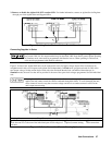
Remote Voltage Sensing
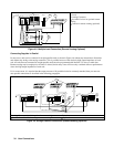
Optional Remote sense connections are illustrated in most of the load diagrams. Remote sensing is accomplished by
connecting the remote sense terminals of the Agilent SAS directly to the load rather than to the output terminals. This allows
the unit to automatically compensate for the voltage drop in the load leads as well as to accurately read back the voltage
directly across the load.
In Fixed mode, the maximum allowable load lead drop that can be compensated for by remote sensing is 2 V.
In Simulator and Table mode, the maximum allowable voltage drop in the load leads is 2 V + (Voc - Vmp).
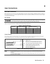
The Agilent SAS is shipped with the switch in the Local position. Remote sensing is obtained by placing the SENSE switch
(see Figure 4-3) in the Remote position. Connect the positive side of the load to the +S analog connector pin and the
negative side of the load to the -S analog connector pin (see Figure 4-1). Connect the sense leads carefully so that they do
not become open-circuited. If sense leads are left open during operation, the unit will regulate at the output terminals instead