


118 Digital Port Functions
GPIB
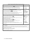
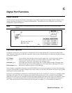
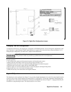
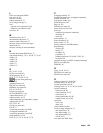
Figure C-2. Example of Inhibit Input
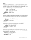
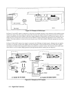
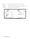
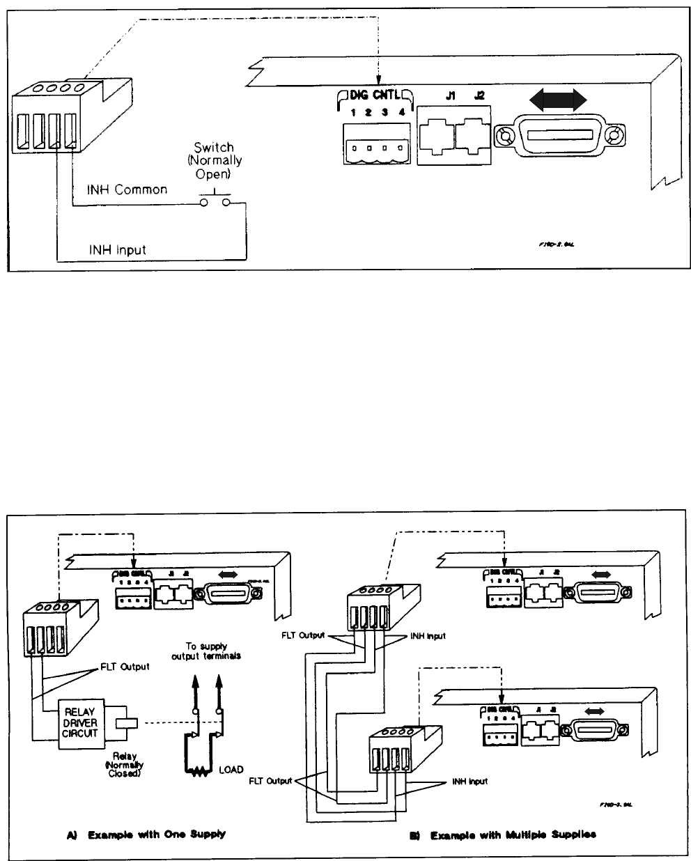
In Figure C-3A, the FLT output is connected to a relay driver circuit that energizes a relay whenever a fault condition occurs
in the power supply. The relay can be used to physically disconnect the output of the power supply from the load. The FLT
output is generated by the logical ORing of the power supply’s Operation, Questionable, and Event status summary bits (see
chapter 8). You can cause one or more events to activate the FLT output by enabling the appropriate events in these status
registers. The fault condition is cleared by first removing the cause of the fault and then reading the appropriate status event
register(s).
In Figure C-3B, the FLT output of one supply is connected to the INH input of another supply. Although only two supplies
are shown, it is possible to chain other supplies with this arrangement. A fault condition in any one of the power supplies
will disable all of them without intervention either by the controller or external circuitry. The controller can be made aware
of the fault via a service request (SRQ) generated by the Questionable Status summary bit (see chapter 8).
GPIB GPIB
GPIB
Figure C-3. Examples of FLT Outputs