


Turn-On Checkout 25
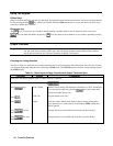
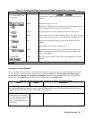
Table 3-1. Checking the Voltage Functions with Output Terminals Open (continued)
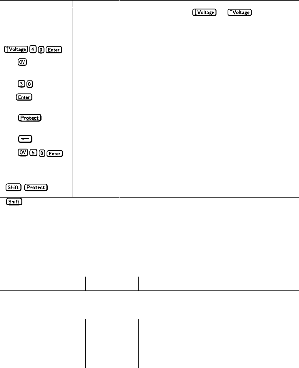
Procedure Display Explanation
Rotate the Voltage control
first counterclockwise and
then clockwise
Control operates similarly to
and keys. The control
is rate sensitive. Turning it more quickly causes a more rapid change in
voltage.
Press
40.00 Program the output to 40 volts.
Press
Display shows default OVP (overvoltage protection) trip voltage for your
unit (see Supplemental Characteristics in appendix A).
Press
OV 30 Program the OVP to 30 volts, which is less than the output voltage.
Press 0.000 OVP voltage entered is less than the output voltage. This causes the OVP
circuit to trip. The output drops to zero, CV turns off, and Prot turns on.
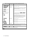
Press
OV - - - - - Shows that the Agilent SAS shuts down because the OVP circuit has
tripped.
Press
Return display to meter mode (optional step).
Press
0.000 Program the OVP to 50 volts, which is greater than the output voltage.
Note: You cannot clear an OVP trip until you have first removed the
cause of the condition.
Press Prot Clear
(
)*
40.00
The OVP circuit is cleared, restoring the output. Prot turns off and CV
turns on.
* is the unlabeled blue key.
Checking the Current Function
The tests in Table 3-2 check the basic current functions with a short connected across the Agilent SAS output. These tests
are possible only from the front panel when the unit is operating in Fixed mode. Do not program maximum output
currents unless the shorting wire is capable of handling the current (see Supplemental Characteristics in appendix A
and table 4-1). The AMPS display will show various readings. Ignore the VOLTS display.
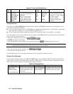
Table 3-2. Checking the Current Functions with Output Terminals Shorted
Action Display Explanation
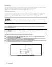
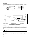
Turn off the Agilent SAS and connect a #18 AWG or larger wire across the output (+) and (-) terminals. If you intend to
test at full-rated output current, use a wire or wires of sufficient size to carry the maximum current of the unit (see
Supplemental Characteristics in appendix A and table 4-1 in Chapter 4).
Turn on the unit.
Set the voltage to its maximum
value. This example assumes that
you have an 60-volt unit (see
Table 7-3 for the value for your
specific unit).
Meter mode
Essentially zero outputs with Dis annunciator on.