


108 Verification and Calibration
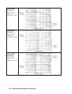
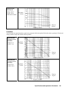
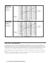
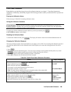
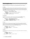
Table B-4. Operation Verification Test Parameters (continued)
Test Description Minimum Spec Results * Maximum
Spec
Measurement
Uncertainty
MODEL Agilent E4351B
Voltage Programming and Readback
Low Voltage (0 V) -20 mV V
DVM =
______ mV +20 mV
2.0
µ
V
Front Panel Display Readback V
DVM
-84 mV V
FP =
______ mV V
DVM
+84 mV
2.0
µ
V
High Voltage ( 60 V) 119.89 V V
DVM =
______ V 120.11 V 1.7 mV
Front Panel Display Readback V
DVM
-180 mV V
FP =
______ mV V
DVM
+180 mV 1.7 mV
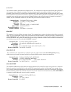
Current Programming and Readback
Low Current (0 A) -10 mA I
DVM =
______ mA +10 mA
15
µ
A
Front Panel Display Readback I
DVM
-14 mA I
FP =
______ mA I
DVM
+14 mA
15
µ
A
High Current (8 A) 3.982 A I
DVM =
______ A 4.018 A
586
µ
A
Front Panel Display Readback I
DVM
-22 mA I
FP =
______ mA I
DVM
+22 mA
586
µ
A
* Enter your test results in this column.
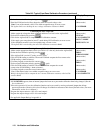
Calibration
Important The Agilent SAS can only be calibrated in Fixed mode. Mode switching is accomplished over the
GPIB bus via the SCPI CURRent:MODE command.
The Agilent SAS may be calibrated either from the front panel or from a controller over the GPIB. The procedures given
here apply to both models. The recommended calibration interval is once a year. Note that these instructions do not include
verification procedures. If you need to perform verification as a prerequisite to or as part of your calibration procedure, see
“Verification”.
Test Equipment Required
The equipment listed in Table B-1, or equivalent, is required for calibration.
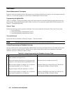
General Procedure
Because the Agilent SAS output must be enabled during calibration, voltages or currents
hazardous to personnel and/or damaging to equipment can appear at the output terminals.
Parameters Calibrated
The following parameters may be calibrated:
•
Output voltage.
• Output voltage readback.
• Overvoltage protection (OVP).
• Output current.
• Output current readback.
You do not have to do a complete calibration each time. If appropriate, you may calibrate only the voltage or current and
proceed to "Saving the Calibration Constants".
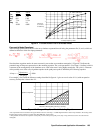
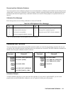
Figure B-1 shows the test setups required for voltage and current calibration.