Appendix C. Frame Relay Examples
C-8 ATLAS 550 User Manual 61200305L1-1
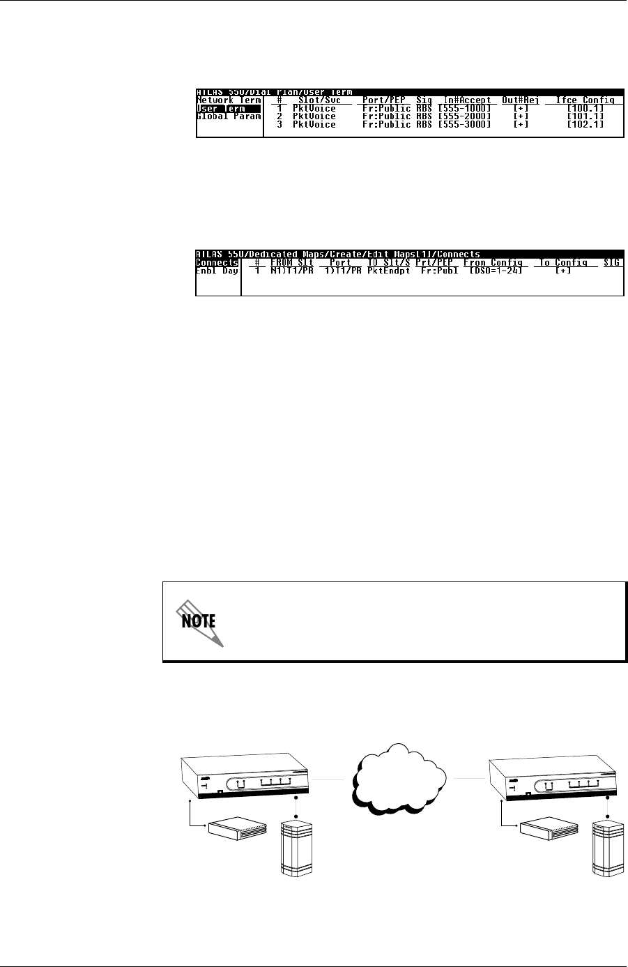
Step 4 Configure the dial plan for packet voice. Refer to Chapter 11, Dial Plan for
details on configuration (see Figure C-22).
Figure C-22. Menu for Configuring Dial Plan
Step 5 Connect the packet endpoint to the physical interface (see Figure C-23).
Figure C-23. Menu for Connecting Packet Endpoints
Example 5: Private Frame Relay Network—Packet Voice
Example 5 (see Figure C-24) shows a private frame relay network using
compressed voice. An ATLAS 550 is located at two sites (Atlanta and
Boston)andaPBXisconnectedtoeachATLAS550usingaclear-channelT1
connection. Each PBX uses DS0s 1—23 for voice and DS0 24 for signaling; all
calls are to be completely managed by the PBXs. In this network, the ATLAS
550 does notterminate the signaling information, but forwards the signaling
between endpoints using a transparent bit oriented protocol (TBOP) frame
relay connection (requires the Voice Compression Module). To re-create this
example, follow the process discussed below.
Figure C-24. Private Frame Relay Network Using Compressed Voice
Packet voice transmission requires the V
OICE
C
OMPRESSION
M
ODULE
.
Router
PBX
Atlanta
Router
PBX
Boston
Private
Frame Relay
Network
P
O
W
E
R
RE
M
O
TE
ER
R
O
R
TE
ST
O
K
TE
ST
O
N
L
IN
E
S
T
A
TU
S
E
R
R
O
R
TE
S
T
O
K
C
R
A
FT
A
C
O
A
LA
R
M
A
LA
RM
1
2
N
E
TW
O
R
K
1
2
3
4
M
O
D
U
LE
S
SY
S
TE
M
E
TH
E
RN
ET
A
T
L
A
S
5
5
0
ATLAS 550
ATLAS 550
P
O
W
E
R
R
E
M
O
T
E
E
R
R
O
R
T
E
S
T
O
K
TE
S
T
O
N
L
IN
E
S
T
A
T
U
S
E
R
R
O
R
T
E
S
T
O
K
C
R
A
F
T
A
C
O
A
L
A
R
M
A
LA
R
M
1
2
N
E
T
W
O
R
K
1
2
3
4
M
O
D
U
LE
S
S
Y
S
T
E
M
E
T
H
E
RN
E
T
ATLA
S
5
5
0


