


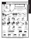
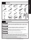

Tools Needed:
Please Do Not Return This Product To The Store. Contact your local Wayne-Dalton dealer. To find your local Wayne-Dalton dealer, refer to your local
yellow pages business listings or go to the Find a Dealer section online at www.Wayne-Dalton.com
7
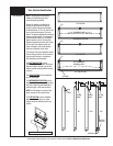
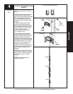
PRE-INSTALLATION
Fig. 2
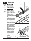
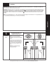
A TorqueMaster
®
spring system can be
identified by the end brackets. For single
spring applications, the right hand end
bracket will always have a drive gear,
counter gear, counter cover, and a winding
bolt head. The left hand end bracket will
have no gears, counter cover, or winding
bolt head. The hole for the winding bolt
head will be plugged.
For double springs, both the right hand
and left hand end brackets will always
have a drive gear, counter gear, counter
cover and a winding bolt head.
IMPORTANT: RIGHT AND LEFT HAND IS
ALWAYS DETERMINED FROM INSIDE THE
BUILDING LOOKING OUT.
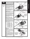
Step 1: If you have a black counter cover:
Place a mark on the drive gear tooth and an
adjacent mark on the right hand end bracket
(Fig. 1). Loosen the lock nut using a 7/16”
wrench and continue with step 2.
If you have a gray counter cover: Loosen
the lock nut using a 7/16” wrench and
continue with step 2.
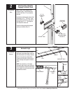
Step 2: Using an electric drill (High
torque / gear reduced to 1300 rpm
preferred) with a 7/16” hex head driver,
unwind the right hand winding bolt head
counterclockwise (Fig. 2) and count the
number of turns the mark on the drive
gear passes the adjacent mark on the end
bracket. Referencing the chart below, by
door height, stop unwinding the spring
once the counted turns have reached the
listed number of turns.
6’-0” Door Height = 14 turns
6’-3” Door Height = 14 1/2 turns
6’-5” Door Height = 15 turns
6’-6” Door Height = 15 turns
6’-8” Door Height = 15 1/2 turns
6’-9” Door Height = 15 1/2 turns
7’-0” Door Height = 16 turns
7’-3” Door Height = 16 1/2 turns
7’-6” Door Height = 17 turns
7’-9” Door Height = 17 1/2 turns
8’-0” Door Height = 18 turns
CAUTION:
DO NOT USE IMPACT GUN TO
UNWIND SPRINGS.
IMPORTANT: DO NOT REFERENCE THE
COUNTER COVER WHEN COUNTING THE
NUMBER OF TURNS BEING UNWOUND
ON THE SPRING, BUT FOLLOW THE
INSTRUCTIONS ABOVE.
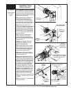
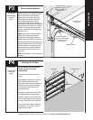
Step 3: Verify that spring tension has been
released by pulling the counterbalance
cable on the right hand cable drum away
from the header (Fig. 3). If spring tension
has been released, the cable will be loose.
In addition, the TorqueMaster
®
Spring
Tube should be free to rotate in either
direction.
Fig. 1
Fig. 3
Fig. 4
RIGHT HAND
CABLE DRUM
TORQUEMASTER
®
SPRING TUBE
CHECK CABLE
TENSION
LOOSEN LOCK
NUT
COUNTER
GEAR/ COVER
RIGHT HAND
END BRACKET
PLACE MARK ON END BRACKET
AND DRIVE GEAR TOOTH
BEFORE UNWINDING SPRINGS
END BRACKET
RIGHT HAND
WINDING BOLT HEAD
ELECTRIC DRILL
WITH 7/16” HEX
DRIVER (DO NOT
USE IMPACT
GUN)
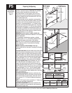
PRY COUNTER GEAR
AND COUNTER COVER
FROM END BRACKET
USING FLAT TIP
SCREWDRIVER
COUNTER
GEAR
COUNTER
COVER
TorqueMaster
®
Spring Removal
P2
Recommended
tools from
page 5