


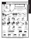
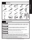

Tools Needed:
Please Do Not Return This Product To The Store. Contact your local Wayne-Dalton dealer. To find your local Wayne-Dalton dealer, refer to your local
yellow pages business listings or go to the Find a Dealer section online at www.Wayne-Dalton.com
6
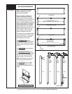
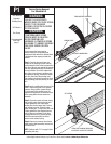
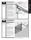
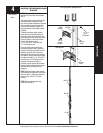
APPROVED WINDING BAR
TORSION SPRING ASSEMBLY
WINDING CONE
SET SCREWS
FIRMLY HOLD WINDING BARS AND
CAUTIOUSLY LOOSEN SET SCREWS
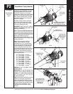
P1
Approved
Winding Bars
3/8” Wrench
Vice Clamp
Recommended
tools from
page 5
FAILURE TO USE APPROVED
WINDING BARS CAN CAUSE SPRING
ENERGY TO BE RELEASED
SUDDENLY, RESULTING IN SEVERE
OR FATAL INJURY.
COUNTERBALANCE SPRING
TENSION MUST BE RELIEVED
BEFORE REMOVING ANY
HARDWARE. A POWERFUL SPRING
RELEASING IT’S ENERGY SUDDENLY
CAN CAUSE SEVERE OR FATAL
INJURY.
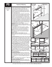
Do not release the torsion spring
tension unless you are qualified and
experienced door technician. Instead have
a professional door agency release the
tension.
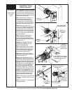
Step 1: Close the door and place vice
clamps on the back legs of both vertical
tracks, above the third roller to prevent the
door from lifting as you unwind the springs.
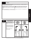
Use only approved winding bars available
from your dealer. Do not use undersized
steel rods, screw drivers or anything else
to unwind the springs. Position the ladder
just off to the side of the winding cone.
The winding cone should be easy to reach
without putting your body directly in front
of it.
Step 2: Insert a winding bar into one of the
holes in the winding cone. Exert upward
pressure. Using caution, loosen the two
(2) set screws in the winding cone. Be
prepared to support the full torsional force
of the spring when the set screws are
loosened.
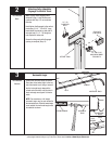
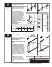
Step 3: Once set screws are loose, slowly
and carefully lower the winding rod until
it rests against the door. Insert other
winding bar into the upper hole. Push up
and remove lower bar. Carefully lower
upper winding bar, 1/4 turns at a time until
it rests against the door. Repeat process
until all tension is relieved. If your door
is equipped with two (2) torsion springs,
follow the same procedure to relieve
tension on the second spring.
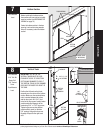
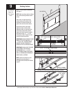
Step 4: Remove vice clamps from tracks,
unbolt torsion shaft assembly and remove
from work area.
NOTE: Continue with “P4” on page 9 after
completing this step.
Torsion Spring Removal
For Standard Lift
WARNING
WARNING