7
VFR-400 • 5403548 • REV D • 10/07
LCD
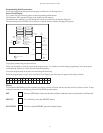
A 2 line 32 character alpha-numeric liquid crystal display shows the condition, status and circuit for all
Alarm, Supervisory and Trouble conditions:
CONDITION STATUS CIRCUIT
Alarm <user Defi ned Message> (Up To 10 Characters)
Trouble Disabled Output #1
Supervisory Acknowledged Output #2
Tamper Silenced Output #3
Low Air Output #4
High Air Battery
Aborted A.C.
Pre-discharging Supervisory
Releasing Zone #1
Released Zone #2
Zone #3
Zone #4
Ground
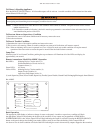
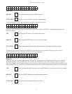
VFR-400 Visual Indicators
In accordance with ULC S527-99 option B:
LED Annunciator Module
Red LED’s: Initiating Device Circuits Active (4),
Notifi cation/Release Circuits Active (4)
Common Alarm (1)
Green LED: AC Power
Yellow LED’s: Initiating Device Circuits Troubles (4),
Output Circuits Troubles (4)
Supervisory Initiating Zone (4)
Supervisory Bell Output Active (4)
(1) each: Supervisory Zone, Supervisory 1, Supervisory 2, Power Trouble, Supervisory Trouble, System
Trouble, Ground Fault, Discharging/Discharged, Alarm Silenced
CONDITION STATUS LED State
Trouble Non-Silenced Flashing
Trouble Silenced Steady ON
Alarm Non-Silenced Flashing
Alarm Silenced Steady ON
Supervisory Non-Silenced Flashing
Supervisory Silenced Steady ON
Pre-discharge Flashing
Discharged Steady ON
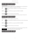
Control Buttons
• Signal Silence - Momentary, silences signaling circuits, (except those activated by zones programmed as WATERFLOW)
• System Reset - Momentary, resets all alarm circuits if condition has been corrected, removes power from initiating device circuits.
• Scroll Up - Scrolls LCD display to most recent events
• Scroll Down - Scrolls LCD display to previous events
NOTE: Buzzer silence is accomplished by scrolling through all events.
Circuit Parameters
All voltages regulated DC
Initiating Device Zones
For connection of dry contact initiating devices and compatible 2 wire smoke detectors. (All values nominal)
• 4 Class B, Style B (Class A Style D module available)*
• Power limited, current limited to protect 2 wire smoke detectors
• Maximum 2 wire 24VDC smoke detector load per zone - 2.5 ma (Use only detectors that are listed in compatibility list.)
• Maximum Line resistance - 100 ohms (Except linear heat detection cable, 700 ohms per zone)
• End-of-Line Resistance - 5.1K


