12
VFR-400 • 5403548 • REV D • 10/07
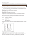
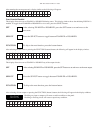
To Silence A Signaling Appliance
Press the SIGNAL SILENCE button. All silencable outputs will de-activate. A trouble condition will be created and the amber
Alarm Silenced LED will light.
Notes: 1) Alarms initiated from zones that are in the waterfl ow mode cannot be silenced. The panel must be reset to silence
audible alarm devices.
2) If silenceable waterfl ow indication is desired it must be programmed as conventional alarm and annunciated on the
zone identifi cation portion of the LCD.
To Reset an Alarm or Supervisory Condition
1) Determine the cause of the alarm condition and if necessary remove the cause.
2) Press the reset button.
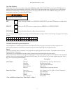
To Reset A Trouble Condition
1) Determine the cause of the trouble condition and remove the cause.
2) This circuit is self-restoring. When all trouble conditions are removed all indications will return to normal.
Note: When an initiating device zone is operated in a Class A (Style D) mode any trouble condition will require manual
operation of the reset switch to restore the panel to normal after the fault has been corrected.
Lamp Test
When the panel is in a Normal Condition, pushing the top two buttons will illuminate all of the LED's and display for
approximately one second.
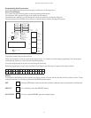
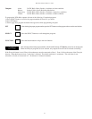
Remote Annunciator Model RA-4410RC Operation
Red LED’s: Initiating Device Circuits Active (4)
Notifi cation/Release Circuits Active (4)
Common Alarm (1)
Green LED’s: AC Power
Yellow LED’s: Initiating Device Circuits troubles (4)
Output Circuit Troubles (4)
supervisory Bell Output Active (4)
(1) each: Supervisory Zone, Power Trouble, Supervisory Trouble, System Trouble, Ground Fault, Discharging/Discharged, Alarm Silenced
RA-4410RC
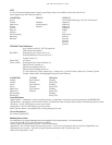
Where audible and/or visual indicators are being used as an evacuation signal, do not silence an alarm condition without
investigating and determining that an emergency condition does not exist.
ZONE 1
ZONE 2
ZONE 3
ZONE 4
OUTPUT 1
OUTPUT 2
OUTPUT 3
OUTPUT 4
AC POWER
POWER TBL
SYSTEM TBL
SUP TBL
GROUND FAULT
SUPERVISORY 1
SUPERVISORY 2
COMMON ALARM
ALARM SILENCE
STEADY: DISCHARGE
FLASHING: PRE-DISCHARGE
LAMP TEST
DWG# 3550-17VKG
Basic Operation
The appropriate LED fl ashes to indicate a change of status on the panel. A trouble or supervisory condition will fl ash
the appropriate Yellow LED indicating the location of the condition. If any outputs are programmed as TROUBLE or
SUPERVISORY BELL, that Yellow output LED will fl ash indicating the output is activated. Pressing the BUZZER SILENCE
button on the panel changes the fl ashing zone Amber LED to steady on and turns the fl ashing Yellow output LED off.
An alarm or low air alarm condition will fl ash a Red LED indicating the zone in alarm and any outputs mapped to that zone that


