32
VFR-400 • 5403548 • REV D • 10/07
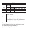
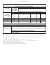
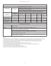
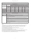
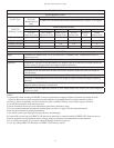
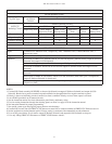
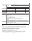
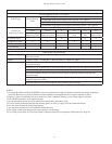
XX = Cross-Zoned
PROGRAM #7
For One Sprinkler System
Viking Sprinkler
System Types
2 Cross Release
Zones and
Manual Release
Zone
1. FIRECYCLE III Double Interlocked Preaction Multicycle System
2. FIRECYCLE III Double Interlocked Preaction Multicycle System - NYC Special
OUTPUTS
(Indicating Circuits)
ZONES (Initiating Circuits)
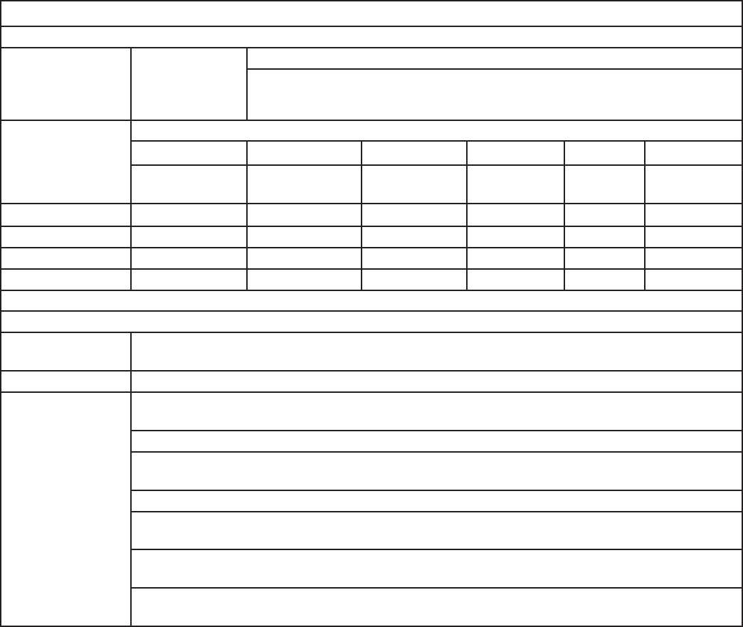
SUP 1 SUP 2 #1 #2 #3 #4
Low Air
Supervisory Zone
Valve Tamper
Supervisory Zone
FIRECYCLE
Detector Zone
Low Air
Alarm Zone
Waterfl ow
Zone
Manual
Release Zone
#1 General Alarm X X X
#2 Supervisory Bell X X X
#3 Release Solenoid X X X X X
#4 N/O Solenoid X X
OPERATION DESCRIPTION
Inputs: 1 FIRECYCLE Detector zone, 1 Low Air Alarm zone, 1 Waterfl ow zone, 1 Manual Release zone, 2
Supervisory zones
Outputs: 1 General Alarm, 1 Supervisory Bell, 1 Release Solenoid, and 1 N/O Solenoid
Operation: Simultaneous activation of both the FIRECYCLE Detector zone #1 and the Low Air alarm zone #2 will
activate output #1 (General Alarm) and output #3 (Release Solenoid)
Activation of FIRECYCLE Detector zone #1 will activate output #1 (General Alarm)
Activation of Low Air Alarm zone #2 alone will activate output #2 (Supervisory Bell) and output #4
(N/O Solenoid)
Activation of Waterfl ow zone #3 will activate output #1 (General Alarm) and output #4 (N/O solenoid)
Activation of Manual Release zone #4 will activate output #1 (General Alarm) and output #3 (Release
Solenoid)
Deactivation of FIRECYCLE Detector zone #1 will start soak timer, when timer cycle is complete the
output #3 (Release Solenoid) is deactivated.
Activation of Low Air Supervisory zone #1 or Valve Tamper Supervisory zone #2 will activate output #2
(Supervisory Bell)
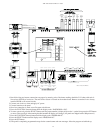
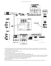
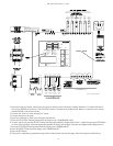
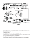
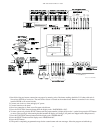
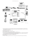
NOTES:
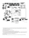
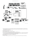
1. Connect EOL Diode assembly IN SERIES as shown with Solenoid on output #3 (Release Solenoid) and output #4 (N/O
Solenoid). Black wire to positive terminal on panel and Red wire through Solenoid to negative terminal on panel.
2. Polarity is shown on indicating circuits in normal (no alarm) condition. Polarity reverses when ouptut is activated.
3. Leave EOLR (provided) on all unnused circuits.
4. See the instruction manual for circuit information, panel limits, and battery sizing.
5. For wire routing instructions through the releasing panel, see Note 3 on page 56 of the instruction manual.
6. See instruction manual for proper programming.
7. See specifi c system type data page for proper pressure switch settings.
8. Connect EOL resistor after last FIRECYCLE detector on return line to common terminal in FIRECYCLE Detector zone #1.
9. Set the soak timer to desired duration period. Factory setting is continuous. Recommend 60 seconds minimum.
10. Loss of DC power below 20 volt causes output #3 (Release Solenoid) to drop out.
11. Use only Viking FIRECYCLE detectors on FIRECYCLE Detector zone #1.


