56
VFR-400 • 5403548 • REV D • 10/07
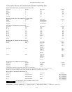
Automatic Water Control Valves Compatibility Data
Viking:
13215 Normally open
11591 Normally closed
11601 Normally closed
11602 Normally closed, explosion-proof
11595 Normally open
11596 Normally open, explosion-proof
11592 Normally closed, explosion-proof
13843 Normally closed
13844 Normally closed, explosion-proof
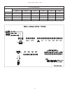
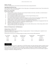
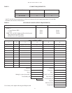
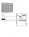
Releasing Device Compatibility
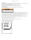
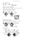
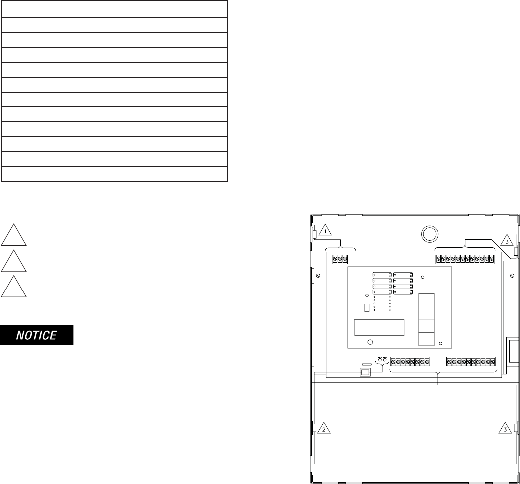
1 Power Inputs
2 Battery Leads
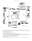
3 Using The Cable Clamps Provided, Route All Other Wiring Away
From Power Input Wiring.
All fi eld installed wiring connected to this panel must maintain a spacing
of 1/4" between all electric light, power, class 1 or non-power limited fi re
protective signaling conductors.
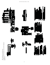
Wire Routing for VFR-400
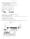
ZONE 1
ZONE 2
ZONE 3
ZONE 4
OUTPUT 1
OUTPUT 2
OUTPUT 3
OUTPUT 4
PROGRAM
MODE
RUN
MODE
AC POWER
POWER TBL
SYSTEM TBL
SUP TBL
GROUND
FAULT
SUP 1/ABORT
SUPERVISORY 2
COMMON ALARM
ALARM SILENCE
STEADY: DISCHARGED
FLASHING: PRE-
DISCHARGE
RUN
PROGRAM
SET
SELECT
FUNCTION
SCROLL-DOWN
BUZZER SILENCE
SIGNAL SILENCE
SYSTEM RESET
SCROLL-UP
BUZZER SILENCE
VIEWING ANGLE
RED OUTPUT LED STEADY: ABORT
DWG# 3550-16


