58
VFR-400 • 5403548 • REV D • 10/07
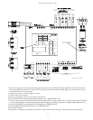
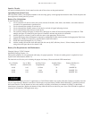
** Or other UL864 9th Edition listed stand alone DACT connected as shown and installed in the same room within 20 feet of the
VFR-400 and with interconnecting wiring in conduit.
See PFC-7500 Manual 8910225 for programming information.
See PFC-7500 Manual 8910227 for installation instructions.
Note:PFC-7500 requires RA-7690 LCD Annunciator for programming.
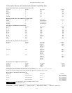
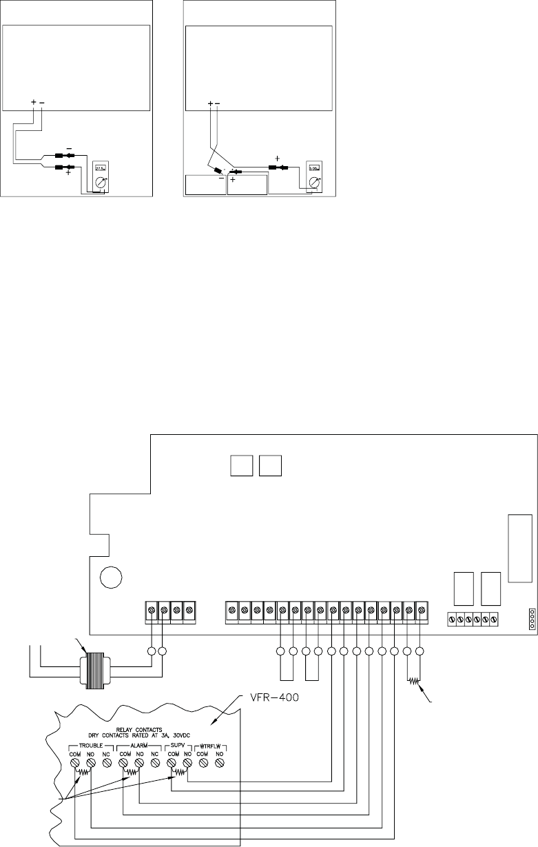
The VFR-400 and PFC-7500 shall be installed in the same room within 20 feet of each other and the interconnecting wires shall be in conduit.
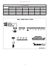
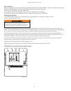
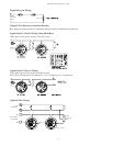
1) To measure the battery charging voltage:
Place a voltmeter across the battery terminals as shown in FIG. 4
2) To measure the battery charging current:
Place a current meter in series with the battery terminals as shown in FIG. 5.
DWG# 3527-9
VOLT
METER
CURRENT
METER
PA N E LPA N E L
ZONE 2
ZONE 3
ZONE 4
120 VAC
60 HZ
350mA
3.3K EOLR
3.3K EOLR'S FROM PFC-7500
WLT
TRANSFORMER
AC MODE
AC AC
B+
BO
RED YEL
GRN
BLK Z1A+ Z1A- Z1B+ Z1B- Z2+ Z2- Z3+ Z3- Z4+ Z4- Z5+ Z5-
N/CCOM N/ON/CCOMN/O
OUTPUT 1
OUTPUT 2
EPROM SOCKET
J11
J12
1
2
3
4
U21
TELEPHONE CONNECTIONS
MAIN
BACKUP
J4 J5
PFC-7500
SS SSSSSSSSSSSS
ZONE 1
Connection Procedure for Battery Charging Current and Voltage
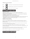
Connection Drawing for Central Station and Remote Station Operation
VFR-400/PFC-7500 Interconnection Drawing


