50
VFR-400 • 5403548 • REV D • 10/07
Wire Checkout:
With all initiating devices and notifi cation appliances installed and with the EOLR’s in place, check the wires with an
ohmmeter. Meter readings outside of the following will prevent normal operation.
From any wire to ground – less than 100K ohms.
Across the 2 wires on each Initiating zone – between 1.8K ohms and 5.4K ohms.
Across the 2 wires on each notifi cation circuit – between 1.8K ohms and 23.9K ohms.
Mounting Instructions:
1) The unit should be mounted in a convenient location, approximately 5 ft. from the fl oor where it will be
accessible for testing and servicing.
2) The main circuit board module should be removed before attempting to mount the cabinet. Disconnect the AC power from
TB201. To remove the module, remove the two screws holding the chassis to the cabinet. Lift the module upwards, approximately
1/2", in order to clear the cross-beam of the cabinet on which the module rests. Remove the module and set aside.
3) Install all required conduits, external wiring and devices and make all connections that are external to the panel. Replace
the module. With the AC power still turned off at the circuit breaker panel, connect the AC hot, neutral and ground wires to the
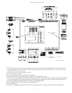
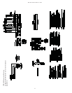
terminal block TB201 as shown on the connection drawing. (See connection drawings on page 54)
4) Connect all the other wiring to the terminals as shown in the connection drawings. Turn the AC power on and connect the
standby batteries with the cable provided, polarity must be observed.
5) Replace false front panel and secure with mounting screws.
6) The operation of the complete system should be verifi ed as outlined in the test procedure section.
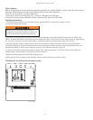
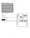
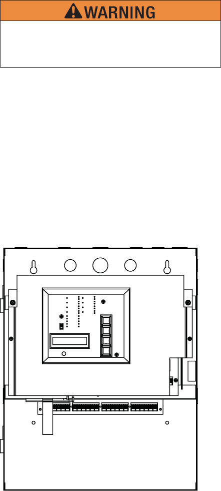
VFR-400 False Front Removal/Assembly Drawing
DWG# 3550-15
Removal of this false front exposes electrical
components at potentially hazardous voltages and
should be performed by qualifi ed personnel only.


