49
VFR-400 • 5403548 • REV D • 10/07
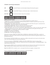
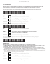
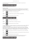
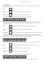
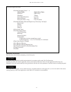
Custom Program (#0 only)
• Describe Initiating Zones 1 - 4
Alarm Zones Supervisory Zones
Detection Supervisory
Waterfl ow Tamper
Linear Heat Detection Low Air
Manual Release High Air
Firecycle (Zone 1 only) Low Air Alarm
• Describe Initiating dedicated Supervisory Zone (Sup 1 & Sup 2)
Supervisory
Tamper
Low Air
High Air
• Select Soak Timer
• Describe Output Zones
Alarm Indicating
Releasing
Supervisory Bell
Trouble Bell
1) Releasing circuits: normal/cross-zoned
2) Discharge time: 7, 8, 9, 10, 20 minutes or continuous
• Map Alarm Inputs to Outputs
• Put in Banner Message
• Put in Banner Message Bottom Line
• Put Zone Description for Each Initiating Zone
• Change Password
• Finished
Installation Instructions
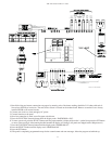
Read the entire manual before attempting to install this panel.
This panel wiring should be installed and maintained in accordance with section 760 (Fire Protection
Signaling Systems) and all other applicable sections of the National Electrical Code, all other applicable NFPA Code and
Standards, local code and the authority having jurisdiction. Review the circuit parameters listed below before installing the panel.
All wiring terminals support 14 to 18 AWG wire sizes. 18 AWG stranded or solid copper wire, (or wire size rated for the current
carrying capacity of the circuit application), with 300V, 85°C insulation is recommended.


