


®
Appendix A Installation checklists
70 BMTK-SVN01D-EN
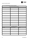
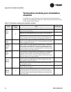
Termination module post-installation
checklist
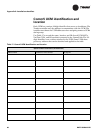
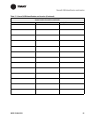
Use Table 18 to verify that the circuits connected to the termination
board on the termination module are wired correctly. Record test results
in the “Actual value” column.
Table 18. Termination module post-installation checklist
Circuit
Mandatory
wiring
Test Actual value
24 Vac
TB1-1,
TB1-2,
TB1-3
9
Measure the voltage between TB1-1 and TB1-2. It must be 24 Vac
nominal (19 Vac to 30 Vac).
Measure the voltage between TB1-1 and TB1-3. It must be approxi-
mately the same voltage as measured between TB1-1 and TB1-2
The ground wire must be connected to terminal TB-3. It must be
tied to building or earth ground at nearest location. Measure the
voltage between TB1-2 and TB1-3. It must be approximately 0 V.
Alarm relay
TB1-4,
TB1-5
Measure the voltage between TB1-4 and TB1-5. It must not exceed
24 Vac. Jumper these two terminals. The user-supplied load should
now be energized and active.
Priority
shutdown
TB1-6,
TB1-7
There must be no voltage applied to these terminals. These termi-
nals must be connected to dry contacts only. Measure the resis-
tance between TB1-6 and TB1-7. It must be approximately 0 Ω with
the user-supplied contacts in the closed position, and infinity ohms
with the contacts in the open position.
Meter input
TB1-8,
TB1-9
There must be no voltage applied to these terminals. The terminals
must be connected to dry contacts only. Measure the resistance
between TB1-8 and TB1-9. It must be approximately 0 Ω with
demand meter contacts in the closed position, and infinity ohms
with the contacts in the open position.
Thermistor
TB1-10,
TB1-11,
TB1-12
There must be no voltage applied to these terminals. The cable
shield must be connected to terminal TB1-12. Measure the resis-
tance between TB1-10 and TB1-11.
Note the approximate temperature at the location of the outdoor
air temperature sensor.
Compare the resistance and temperature values to the listed val-
ues in Table 19 on page 71.
Comm
TB1-13,
TB1-14,
TB1-15
9
There must be no voltage applied to these terminals. Measure the
resistance between TB1-13 and TB1-14. The resistance must be
approximately 50 Ω with daisy-chained wiring. This test confirms
the correct usage of the termination resistors as well as the conti-
nuity of the wire.