


Wire the UCMs
BMTK-SVN01D-EN 35
®
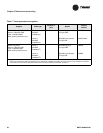
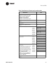
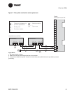
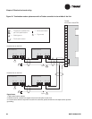
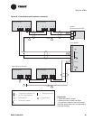
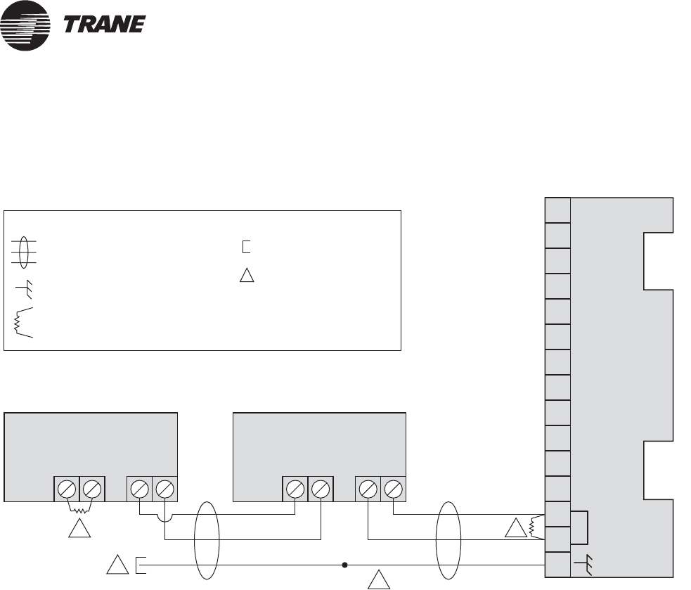
Figure 17. Daisy-chain termination resistor placement
Comm5 device
1
2
3
4
5
6
7
8
9
10
11
12
13
14
15
AAAABBBB
COMM
Comm5 device
Splice
2
1
1
3
Tracker
termination board TB1
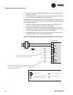
Legend
Twisted pair, shielded wire
perTrane specifications
Shield termination
Shield ground
=
=
=
Figure note
=
Termination resistor
=
(Last device on the link)
Figure Notes:
1105 Ω termination resistor
2 Shield must be cut back and taped at last unit controller.
3 A continuous shield is required. At each unit controller, splice shield wire and tape back to prevent
grounding.