


®
Chapter 3 Termination board wiring
38 BMTK-SVN01D-EN
• The link repeater is limited to 60 devices on either side of the link
(120 devices total).
• The link repeater requires an earth ground. The installer should be
aware of this before making power connections.
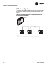
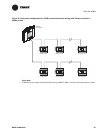
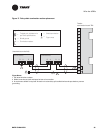
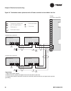
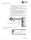
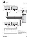
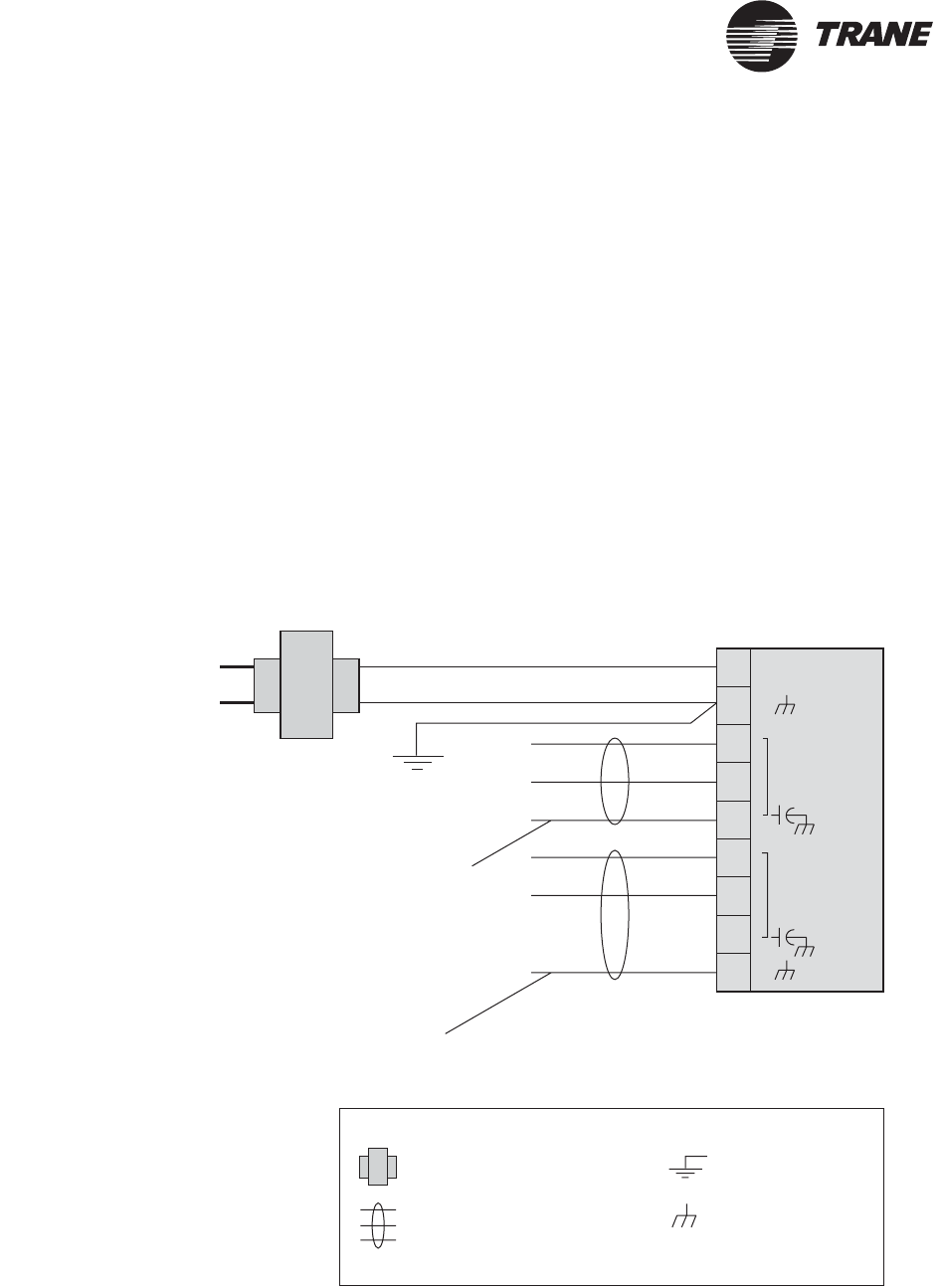
Recommended shield connections are shown in Figure 19. Figure 20 on
page 39 shows a daisy-chain repeater connection. Follow these guidelines
when using a repeater:
• Reference the installation information that comes with the link
repeater (Comm5 repeater installation, 3270 3285).
• Connect the shield-drain wires entering the repeater to a terminal
marked with a capacitor symbol. The entering shield-drain wire must
be connected to earth ground at the Tracker controller.
• Connect the shield-drain wires leaving the repeater to the repeater
terminal marked with an earth ground symbol.
Figure 19. Connecting communication link shield wiring to repeater
Comm
24 VAC
Comm
Link Repeater
24 Vac
Transformer
Earth ground
Entering shield. Continuous run, typically
starting at theTracker controller.
Leaving shield. Must be connected to the earth ground
terminal on the repeater and terminated (insulated from
ground) at the last UCM.
Legend
Twisted pair, shielded wire
perTrane specifications
Earth ground
Transformer
Shield ground
=
=
=
=
2
3
1
4
5
6
7
8
9