


BMTK-SVN01D-EN 55
®
Chapter 7
Troubleshooting
Troubleshooting components
Light-emitting diodes (LEDs) and service pin buttons are used for
troubleshooting the Tracker system.
LEDs
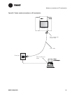
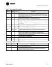
The LEDs on the Tracker controller main logic board and display module
show central processing unit (CPU) status and traffic on the Comm5
communication link, the Ethernet module, and the EIA-232 connection.
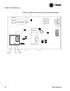
Figure 30 shows the location of the main logic board LEDs; Table 11 on
page 57 provides a description of them. Figure 30 shows the location of
the Ethernet module LEDs; Table 11 on page 57 provides a description of
them. Figure 7 on page 7 shows the location of the alarm LED on the
display module; Table 12 on page 57 provides a description of it.
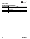
Service pin buttons and jumper
Table 13 on page 58 describes the service pin buttons that are located on
the main logic board. They are used for rebooting the controller and for
Neuron identification. The table also describes the jumper that is on the
main logic board.