


Symptom/action troubleshooting
BMTK-SVN01D-EN 59
®
Symptom/action troubleshooting
Table 14 provides a list of symptoms that indicate a problem in the Tracker system.
For each symptom, the table provides one or more actions that you can perform in an
attempt to resolve the problem.
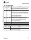
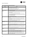
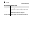
Table 14. Symptom/action troubleshooting
Symptom Action
Tracker controller does not
communicate by modem.
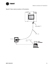
• Verify that the telephone cable is connected to the PC modem port (Figure 24 on
page 48).
• Verify that the phone line is an analog line (not digital).
• Perform the modem self-test procedure from the display module.
Note: The modem is an integral component of the main module and is not field replaceable.
Replacement of the modem requires replacement of the main module.
Tracker controller does not
communicate by EIA-232
port.
• Verify that the cable is connected to the PC direct connect port (Figure 24 on
page 48).
• Verify that the proper cable is used. (Refer to Table 10 on page 47.)
• Verify that the PC workstation is using the Tracker controller software; other com-
munications software will not work.
• Look for activity on the PC RX LED (Figure 30 on page 56).
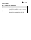
Tracker controller did not
discover UCMs when ini-
tially started.
When the controller is initially powered up, it automatically discovers all communi-
cating UCMs of the proper type and installs them into its database. The discovery
process takes several minutes, depending on how many UCMs are installed on the
communication link.
After the controller has built its database after the initial power up, the controller no
longer automatically discovers UCMs. If you want to initiate the discovery process,
you must do so manually. Initiate the discovery process when a new UCM is added
to the system or an existing UCM is replaced.
• Verify proper wiring of the Comm5 communication link. (UCMs can be discov-
ered only if Comm5 communication has been established.)
• Wait at least 5 minutes for the controller to discover the UCMs.
Note: You can press the service pin button on a UCM at any time to check if it is communicating
with the controller. Pressing the service pin button causes the UCM status LED to flash on and off
(known as “winking”), if the controller is communicating with that UCM.
Touch screen beeps when
touched but does not
progress to the next screen.
Touch screen is out of calibration.
• Perform the procedures for calibrating the touch screen in Tracker Building Auto-
mation System Controller Operations guide (BMT-SVU01A-EN).
Touch-screen back light and
contrast is out of adjust-
ment.
• Perform the adjust brightness and contrast procedure from the display module.
Tracker I/O status is wrong.
• Verify electrical connection using the post-installation checklist (Table 18 on
page 70).
• Verify I/O status as indicated on home display on the display module.
• Display Tracker I/O status self test from display module.