


®
Chapter 7 Troubleshooting
60 BMTK-SVN01D-EN
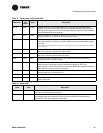
Tracker alarm output is not
working as expected.
• Confirm proper wiring of the alarm relay output. Consult the post-installation
checklist (Table 18 on page 70) for details.
• Initiate the BOP self test from the display module.
Note: The binary output is for alarm notification only. There must be an unacknowledged alarm
present of the proper severity to actuate the alarm output.
Tracker controller will not
communicate with its
UCMs.
• Look for wiring problems (shorts or opens, for example) that develop when wire
is damaged during installation.
• Look for shorts between the two conductors resulting from nicks in the insulating
jacket. (This can be caused by improper technique when stripping away the outer
jacket and shield.)
• Look for a strong source of EMI/RFI interference nearby.
• Look for ac power disturbances from nearby transformers and electrical equip-
ment. This is especially true when running communication links in close proxim-
ity to florescent lighting ballasts.
• Verify the UCM has not failed.
• Verify proper termination resistance.
Tracker processor is locked
up.
• Cycle power to the Tracker main module by removing it from the termination
module.
• If the processor is still locked up after cycling power to the controller, perform a
reboot from the display module or the PC software (if the controller is able to
communicate).
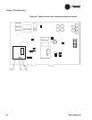
• If the controller will not respond to the above listed methods, push the reset but-
ton (S1) on the main module (see Figure 30 on page 56).
Note: Heartbeat LED (HRT LED5) will be solid green.
Alarm LED on the display is
flashing red.
• At the Tracker controller user interface home screen, push the alarm button on
the display module to acknowledge the alarm, then take the proper corrective
action.
Note: The alarm LED flashes when the controller receives an alarm of the appropriate severity.
Pressing the Alarm button acknowledges the alarm and turns off the flashing LED (until the control-
ler receives another alarm of the appropriate severity).
Tracker controller is annun-
ciating an alarm.
• At the Tracker controller user interface home screen, push the alarm button on
the display module to acknowledge the alarm, then take the proper corrective
action.
Note: The alarm relay energizes when the controller receives an alarm of the appropriate severity.
Pressing the alarm button acknowledges the alarm and turns off the alarm relay output (until the
controller receives another alarm of the appropriate severity).
Display module is not illu-
minated.
• Press anywhere on the touch screen surface to turn the back light on. The control-
ler automatically turns off the back light during extended periods of inactivity to
conserve energy and bulb life.
• Confirm that the controller has 24 Vac power. When the display module has
power, the alarm LED will be either solid green or flashing red.
Display module does not
respond to the touch.
• Confirm that the controller has 24 Vac power. When the display module has
power, the alarm LED will be either solid green or flashing red.
• If the display module is not responding correctly when the display module is
powered up and the back light is on, initiate the touch-screen calibration proce-
dure from the display module.
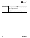
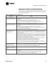
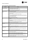
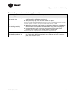
Table 14. Symptom/action troubleshooting (Continued)
Symptom Action