


®
Chapter 3 Termination board wiring
24 BMTK-SVN01D-EN
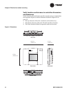
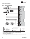
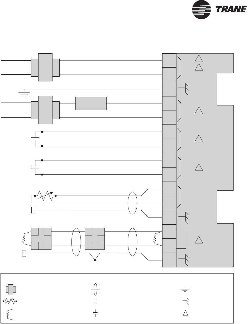
Figure 14. Tracker field wiring connections
24VAC
THERMISTOR
COMM
ALARM
RELAY
PRIORITY
SHUTDOWN
METER
INPUT
1
2
3
4
5
6
7
8
9
10
11
12
13
14
15
24 Vac
Line voltage
Line voltage
Comm5
link
Comm5
link
Comm5 deviceComm5 device
Splice
2
1
3
5
4
4
AA
BB
AA
BB
Legend
Twisted pair, shielded wire
perTrane specifications
Shield termination
Earth ground
Contact points
Thermistor device per
Trane specifications
Transformer
Termination resistor
Shield ground
=
=
=
=
=
=
=
=
LOAD
Figure note
=
Figure Notes:
1 All customer wiring must be in accordance with national, state, and local electrical codes.
2 Trane recommends a dedicated transformer for 24 Vac power.
3 Alarm relay circuit must not exceed 24 Vac, 1 A.
4 Do not apply voltage to the priority shutdown inputs.
5 Example of Comm5 communication link wiring. See product-specific literature for Comm5 wire connection details.