


Wire the UCMs
BMTK-SVN01D-EN 37
®
Wire supported UCMs
Wire the supported UCMs to the Tracker termination board. When
installing communication wire:
• Keep the polarity consistent throughout the site. Although Comm5 is
not polarity sensitive, consistency will improve serviceability.
• Strip away a maximum of 2 inches (50 mm) of the outer conductor
and foil shield when splicing or terminating shielded wire.
IMPORTANT
Use extreme care when stripping away the outer conductor and foil
shield. Be careful not to nick the insulating jacket of the two conduc-
tors. A nick in the insulating jacket will cause communication problems.
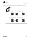
Wire the UCMs as follows:
1. Install termination resistors in the correct locations.
2. Route input wires into the termination module through the conduit
box or any of the conduit openings designated for input and communi-
cation wiring (Figure 12 on page 19).
3. Connect the wires to the COMM terminals on the termination board
(Figure 14 on page 24).
4. Connect the shield to the ground terminal.
5. Connect the other end of the wires to the UCMs, as necessary.
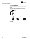
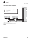
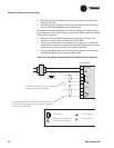
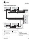
Requirements for repeaters on Comm5 communication
links
The Comm5 communication link repeater is a device that repeats and
regenerates the signal on a Comm5 link in order to enhance signal
quality or extend the length of the run. The Comm5 link goes from the
Tracker controller to the UCMs to the repeater. A second link segment
extends from the other side of the repeater to the rest of the devices. The
configuration on either side of the repeater must be a daisy-chain
configuration. Both link segments require termination.
A link repeater is required when:
• The total wire length is greater than the maximum wire run length of
4593 ft (1400 m) for a daisy-chain configuration.
• More than 60 devices are connected to a link. This total does not
include the Tracker controller, the link repeater, and the possible use
of the Rover service tool on the same link.
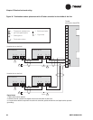
The link repeater has several limitations:
• Only one link repeater can be used on a link.
• The use of a repeater doubles the maximum allowable wire length.
For example, when a repeater is used with a daisy-chain configura-
tion, the total wire length can be 9186 ft (2800 m) (with half the wire
length on either side of the repeater).