


®
Chapter 3 Termination board wiring
34 BMTK-SVN01D-EN
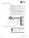
Termination resistor placement for Comm5 links
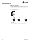
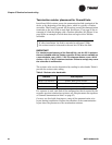
Install one 105 Ω resistor across the communication link terminals of the
device at the beginning of the daisy chain, which is typically a Tracker
controller. Then install a second 105 Ω resistor across the communication
terminals at the last UCM on each link. See Figure 17 on page 35 for an
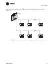
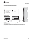
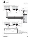
example of a link that begins with a Tracker controller. See Figure 18 on
page 36 for an example of a link that does not begin with a Tracker
controller.
IMPORTANT
For maximum performance of the Comm5 link, use the 105 Ω resistors
that are included with the Tracker controller. If they are not available, as
a second choice, use a 100 Ω, ¼ W, 5% tolerance resistor, or as a third
choice, a 110 Ω, ¼ W, 5% tolerance resistor. Failure to comply may cause
the controller to malfunction.
The resistor value can be determined by reading its color bands. Table 9
provide the resistor color coding.
If a repeater is used, each link of the configuration that is created by the
repeater requires termination resistors (see “Requirements for repeaters
on Comm5 communication links” on page 37).
Create a set of as-built drawings or a map of the communication wire
layout during installation. Ensure that sketches of the communication
layout show the placement of the termination resistors.
Note:
If, after installation, the link is extended to add more UCMs,
the resistor must be relocated to the new last UCM on the link.
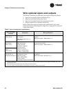
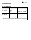
Table 9. Resistor color band table
Toler a n ce Color sequence
105
Ω ± 1% tolerance
Brown, black, green, brown
100
Ω ± 5% tolerance
Brown, black, brown, gold
110
Ω ± 5% tolerance
Brown, brown, brown, gold