


Pro Sweep Page 5 -- 15 Chassis
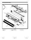
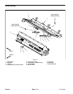
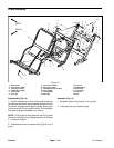
Removal (Fig. 10)
1. Position sweeper on a level surface with dump hop-
per empty and lowered. Have sweeper attached to tow-
ing vehicle, apply vehicle parking brake, stop engine
and remove key from the ignition switch. Chock sweep-
er wheels to prevent sweeper from moving.
2. Remove flange nuts and carriage screws that secure
roller scraper to roller adjustment plates. Remove roller
scraper from machine.
IMPORTANT: When fully lowered, the sweeper is
supported by the roller. To service the roller, raise
the sweeper slightly before carefully loosening fas-
teners that secure roller assembly.
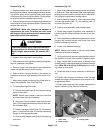
CAUTION
To prevent personal injury, make sure that roller
is supported as it is removed from the machine.
Roller weighs approximately 80 pounds (36.3
kg).
3. Support roller to prevent it from shifting.
4. Note location of roller adjustmentplatesandadjuster
keys for reassembly purposes.
5. Remove flange nuts that secure roller adjustment
plates and adjuster keys to brush housing.
6. Refer to Brush Housing Service in this section for
procedure to remove roller assembly from brush hous-
ing.
7. After raising hopper and placing lift cylinder stop, re-
trieve roller assembly from under machine.
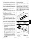
8. To remove bearings from roller:
A. Remove set screw (item 8) that secures locking
collar to roller shaft.
NOTE: Normal roller rotation is counter--clockwise
as viewed from left side of sweeper.
B. Using a punch and hammer, rotate locking collar
(item 7) inthe opposite direction ofnormal roller rota-
tion to loosen collar.
C. Remove carriage screws (item 13), flat washers
(item 11) and lock nuts (item 10) that secure bearing
flanges to roller adjustment plate.
D. Slide bearing flanges, locking collar and bearing
from roller.
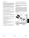
Installation (Fig. 10)
1. Clean roller shaft ends and apply antiseize lubricant
to shaft ends. Place adjustment plate, bearing flanges,
bearing and locking collar onto each end of roller shaft.
Do not tighten set screws in locking collars.
2. Secure bearing flanges to roller adjustment plate
with carriage screws (item 13), flat washers (item 11)
and lock nuts (item 10).
3. Position roller assembly under raised hopper.
4. Slowly lower hopper to position roller assembly to
housing (see Servicing the Brush Housing in this sec-
tion).
5. Secure adjustment plates andadjuster keys to brush
housing with carriage screws and flange nuts using
location noted during removal.
6. Center roller between bearings.
NOTE: Normal roller rotation is counter--clockwise as
viewed from left side of sweeper.
7. Using a punch and hammer, rotate locking collars in
the direction of normal roller rotation to tighten collars.
8. Apply Loctite #242 (or equivalent) to threads of set
screws(item8).Installsetscrewsintocollarsandtorque
from 125to 165 in--lb (14.2 to 18.6N--m) to secure lock-
ing collars to roller shaft.
9. Check that roller is free to rotate and no binding ex-
ists.
10.Position roller scraper to machine. Install carriage
screws and flange nuts that secure roller scraper to roll-
er adjustment plates.
11.Check roller height and roller scraper clearance and
adjust if necessary (see Operator’s Manual).
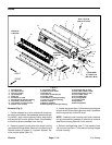
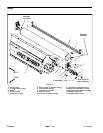
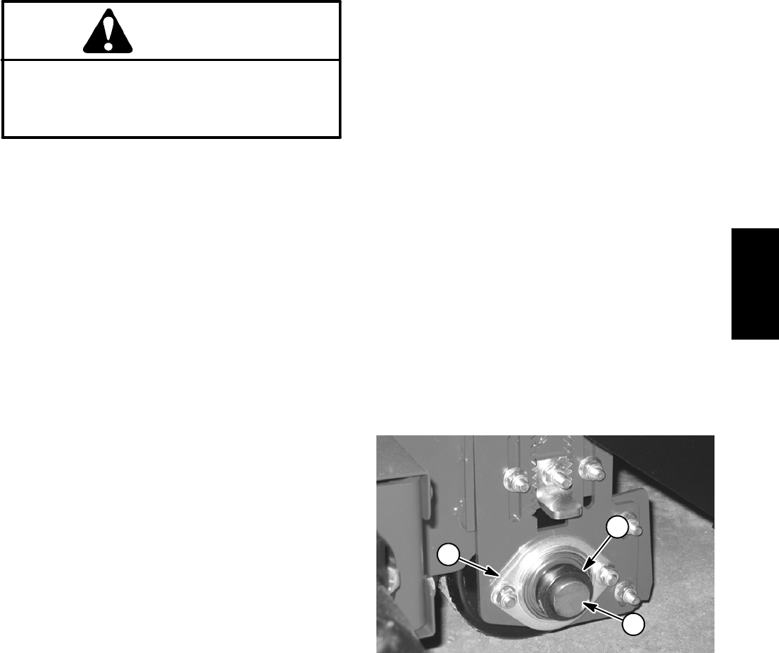
1. Roller shaft
2. Bearing flange
3. Locking collar
Figure 11
2
1
3
Chassis