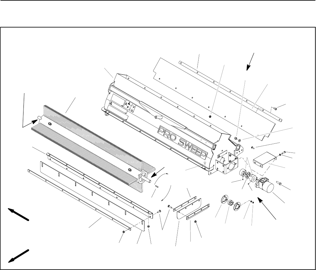
Pro SweepPage 5 -- 10Chassis
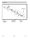
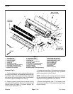
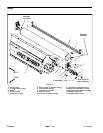
Brush
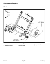
1. Carriage screw
2. Top rubber shield
3. Lock nut (2 used)
4. Top shield plate
5. Flange nut
6. Flat washer (2 used)
7. Carriage bolt (3 used per bearing)
8. Cap screw (4 used per cover)
9. Lock washer (4 used per cover)
10. Coupler cover (2 used)
11. Cap screw (2 used)
12. Hydraulic brush motor
13. Coupler jaw
14. Set screw (2 used per jaw)
15. Coupler spider
16. Flat washer (3 used per bearing)
17. Lock nut (3 used per bearing)
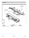
18. Brush housing
19. Bearing assembly
20. Bearing flange (2 used per bearing)
21. Side angle plate (2 used)
22. Side rubber shield (2 used)
23. Side shield plate (2 used)
24. Front rubber shield
25. Front shield plate
26. Front angle plate
27. Carriage screw
28. Square key
29. Brush assembly
Figure 5
FRONT
RIGHT
2
3
1
5
6
7
11
12
13
14
15
16
1
4
5
5
5
17
18
19
20
21
23
24
25
22
26
27
28
29
8
10
9
Loctite #242
61 to 85 in--lb
(6.9 to 9.6 N--m)
Antiseize
Lubricant
Antiseize
Lubricant
14
94 to 116 ft--lb
(128 to 157 N--m)
Removal (Fig. 5)
1. Position sweeper on a level surface with dump hop-
per empty and lowered. Have sweeper attached to tow-
ing vehicle, apply vehicle parking brake, stop engine
and remove key from the ignition switch. Chock sweep-
er wheels to prevent sweeper from moving.
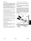
2. Remove hydraulic brush motor from brush housing
(see Hydraulic Brush Motor Removal in the Service and
Repairs section of Chapter 3 -- Hydraulic System). Re-
move coupler spider (item 15).
3. Loosensetscrews(item14)thatsecurecouplingjaw
to brush shaft. Slide coupling jaw from shaft. Locate and
retrieve square key from brush shaft.
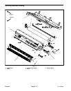
NOTE: If desired, brush housing (with brush installed)
can be removed from sweeper to allow brush removal
(see Brush Housing Removal in this section).
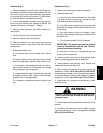
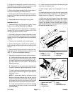
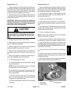
4. Remove carriage bolts (item 7), flat washers (item
16) and lock nuts (item 17) that secure bearing flanges
to brush housing.


