


Pro Sweep Page 5 -- 13 Chassis
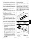
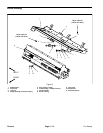
Removal (Fig. 8)
1. Position sweeper on a level surface with dump hop-
per empty and lowered. Have sweeper attached to tow-
ing vehicle, apply vehicle parking brake, stop engine
and remove key from the ignition switch. Chock sweep-
er wheels to prevent sweeper from moving.
2. Remove hydraulic brush motor from brush housing
(see Hydraulic Brush Motor Removal in the Service and
Repairs section of Chapter 3 -- Hydraulic System).
3. Support brush housing to prevent it from shifting.
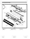
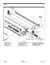
4. Remove cap screws (item 2) and lock nuts (item 3)
that secure pivot mounts to frame.
5. Follow Servicing the Brush Housing procedure in
this section to remove brush housing from saddle frame.
6. After raising hopper and placing lift cylinder stop, re-
trieve brush housing from under machine.
7. Remove cap screw (item 9), flat washer (item 10)
and hardened spacer (item 11) from frontbrush housing
pin.
8. Remove pivot mounts from brush housing. Locate
and retrieve thrust washers (item 7) from between pivot
mount and brush housing.
9. If necessary, remove flange bushings from pivot
mounts. Discard bushings if removed.
Installation (Fig. 8)
1. If flange bushings were removed from pivot mounts,
press new bushings fully into mounts.
2. Place thrust washer and then pivot mount on both
brush housing pins.
3. Secure frontpivot mount withhardened spacer (item
11), flat washer (item 10) and cap screw (item 9).
4. Position brush housing under raised hopper.
5. Slowly lower hopper to position saddle frame to
brush housing (see Servicing the Brush Housing in this
section).
6. Secure pivot mounts to frame with cap screws (item
2) and lock nuts(item 3). Torque lock nutsfrom94to116
ft--lb (128 to 157 N--m) .
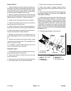
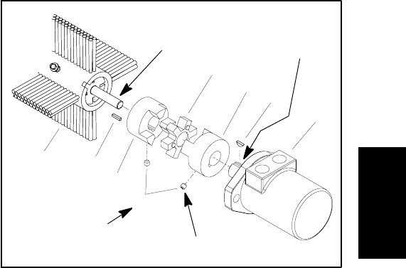
7. Install hydraulic brush motor to brush housing (see
Hydraulic Brush Motor Installation in the Service and
Repairs section of Chapter 3 -- HydraulicSystem).Make
sure thatcoupling jaws have a gap between coupler jaw
valleys from 0.830” to 0.930” (21.1 to 23.6 mm). Apply
Loctite #242 (or equivalent) to threads of coupling set
screws. Secure coupling jaws to motor shaft and brush
shaft by torquing set screws from 61 to 85 in--lb (6.9 to
9.6 N--m) (Fig. 9).
8. Lubricate grease fittings on pivot mounts.
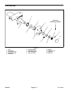
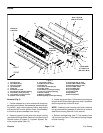
1. Hydraulic brush motor
2. Key
3. Coupling jaw
4. Coupling spider
5. Brush assembly
6. Square key
7. Set screw (2 per jaw)
Figure 9
1
2
3
4
5
6
7
3
61 to 85 in--lb
(6.9 to 9.6 N--m)
Loctite #242
Antiseize
Lubricant
Antiseize
Lubricant
Chassis