


Pro Sweep Hydraulic SystemPage 3 -- 29
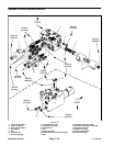
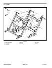
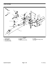
Removal (Fig. 17)
1. Position sweeper on a level surface with dump hop-
per empty and fully lowered. Chock sweeper wheels to
prevent sweeper from moving. If sweeper is attached to
tow vehicle, apply tow vehicle parking brake, stop en-
gine and remove key from the ignition switch.
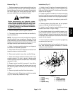
CAUTION
Before disconnecting any hydraulic compo -
nents, operate all sweeper hydraulic controls to
relieve system pressure and avoid injury from
pressurized hydraulic oil. See Relieving Hydrau-
lic System Pressure in the General Information
section of this chapter.
2. Relieve sweeper hydraulic system pressure.
3. Thoroughly clean control manifold and manifold hy-
draulic connections.
NOTE: The ports on the control manifold are marked to
identify hydraulic hose connections. Example: P is the
pump connection port (see Hydraulic Schematic in this
chapter to identify the function of the hydraulic lines and
cartridge valves at each manifold port location).
4. Label all control manifold electrical and hydraulic
connections for assembly purposes.
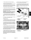
5. Disconnect wire harness electrical connectors from
solenoid valves on control manifold.
6. Disconnect hydraulic hoses from manifold fittings.
7. Allow disconnected hydraulic hoses to drain into a
suitable container. Put caps or plugs on disconnected
hosesandfittingstopreventcontamination.Discardany
removed O--rings.
8. Support control manifold to prevent it from falling.
Remove two (2) cap screws, flat washers and lock nuts
that secure hydraulic manifold to the frame mounting
bracket.
9. Remove hydraulic manifold from the machine.
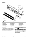
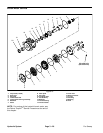
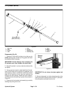
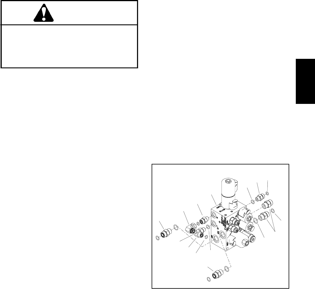
10.Remove hydraulic fittings from manifold as needed
(Fig. 18). Discard any removed O --rings.
Installation (Fig. 17)
1. Lightly oil new O--rings for a ll removed hydraulic fit-
tings. Install hydraulic fittings to control manifold (see
Hydraulic Fitting Installation in the General Information
section of this chapter).
2. Position hydraulic manifold to the frame mounting
bracket. Install cap screws, washers and lock nuts that
secure manifold to frame. Do not fully tighten fasteners.
3. Make sure all hydraulic connections, ports and fit-
tings are clean.
4. Remove caps or plugs that were put on hydraulic
hoses and fittings during manifold removal.
5. Lightly oil new O--r ings for hydraulic fitting and hose
locations and install O --rings in fitting.
6. Using labels placed during manifold removal, cor-
rectly connect hydraulic hoses to the manifold fittings.
Properly tighten all hydraulic connections (see Hydrau-
lic Hose and TubeInstallationintheGeneral Information
section of this chapter).
7. Secure hydraulic manifold to machine by tightening
cap screws and lock nuts.
8. Using labels placed during manifold removal, con-
nect wire harness electrical connectors to solenoid
valves on control manifold.
1. O--ring
2. Hydraulic fitting
3. O--ring
4. O--ring
5. Hydraulic fitting
6. O--ring
7. Hydraulic manifold
8. 90
o
hydraulic fitting
9. 90
o
hydraulic fitting
Figure 18
3
7
5
1
2
1
2
5
5
3
3
4
6
8
9
Hydraulic
System