


Pro Sweep Hydraulic SystemPage 3 -- 33
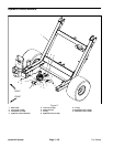
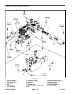
Removal (Fig. 20)
1. Position sweeper on a level surface with dump hop-
per empty and fully lowered. Chock sweeper wheels to
prevent sweeper from moving. If sweeper is attached to
tow vehicle, apply tow vehicle parking brake, stop en-
gine and remove key from the ignition switch.
CAUTION
Before disconnecting any hydraulic compo -
nents, operate all sweeper hydraulic controls to
relieve system pressure and avoid injury from
pressurized hydraulic oil. See Relieving Hydrau-
lic System Pressure in the General Information
section of this chapter.
2. Relieve sweeper hydraulic system pressure.
WARNING
Make sure that sweeper is fully lowered before
loosening hydraulic hose from lift cylinder. If
sweeper is not fully lowered as hoseis loosened,
sweeper may drop unexpectedly.
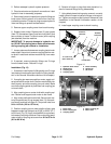
3. Disconnect hydraulic hose from hydraulic fitting on
liftcylinder (Fig. 21). Locate and discardO--ring from be-
tween hose and fitting. Allow hose to drain into as uitable
container.
4. Plug disconnected hoseand lift cylinderfittingto pre-
vent contamination.
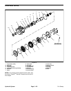
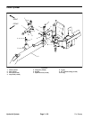
5. Remove lock nuts (item 5) and cap screws (item 3)
that areused to retain lift cylinder pivotpins (items 4 and
7) to sweeper frame.
CAUTION
To prevent personal injury, make sure that lift
cylinder is supported as it is removed from the
machine. Lift cylinder weighs approximately 43
pounds (19.5 kg).
6. Support lift cylinder and slide pivot pins from the lift
cylinder and machine frame.
7. Remove lift cylinder from the machine.
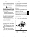
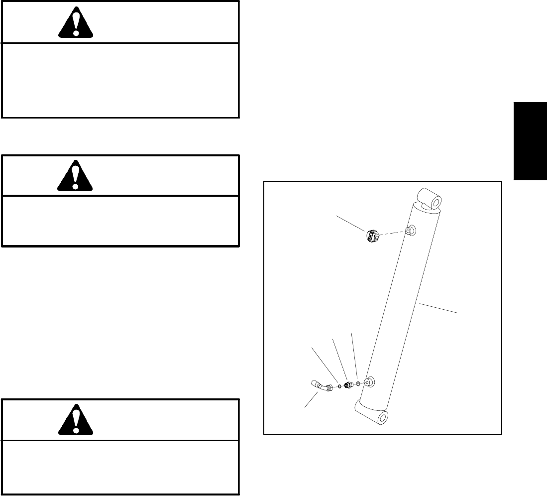
8. If needed, remove hydraulic check valve fitting and
O--ring from the lift cylinder (Fig. 21). Discard O--ring.
Installation (Fig. 20)
1. If removed, install hydraulic check valve fitting and
new O--ring into lift cylinder (Fig. 21) (see Hydraulic Fit-
ting Installation in theGeneralInformationsection of this
chapter).
2. Position lift cylinder to the machine mounting points.
Make sure the port of the lift cylinder faces the front of
the machine.
3. Align lift cylinder mounting holes with frame mounts.
Install pivot pins. Secure pivot pins to frame with cap
screws and lock nuts.
4. Remove plugs from disconnected hose and fitting.
5. Connect hydraulic hose withnew O--ring to hydraulic
fitting on lift cylinder. Tighten hose connection (see Hy-
draulic Hose and Tube Installation in the General Infor-
mation section of this chapter).
6. Lubricate grease fittings on lift cylinder.
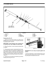
1. Lift cylinder
2. Breather
3. O--ring
4. Check valve fitting
5. O--ring
6. Hydraulic hose
Figure 21
2
3
6
1
5
4
Hydraulic
System