Pro Sweep Page 4 -- 7 Electrical System
Adjustments
Proximity Switches
The Pro Sweep uses five (5) identical inductive proximi-
ty switches tocontrolsweeper operation. These proxim-
ity switches are normally open and close when a
sweeper frame component is positioned near the target
end of the switch. The switches incorporate a LED on
the cable end of the switch. The LED illuminates when
the switch is in the closed position. The switches are
mounted on the main sweeper frame in three (3) loca-
tions. Refer to Proximity Switches in the Component
Testing section for additional switch information.
Proximity Switch Adjustment
1. Position sweeper on a level surface with dump hop-
per empty and lowered. Have sweeper attached to tow-
ing vehicle with the sweeper positioned directly behind
the tow vehicle (not offset). Engage vehicle parking
brake, stop engine and remove key from the ignition
switch. Chock sweeperwheels to preventsweeper from
moving.
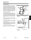
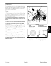
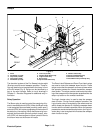
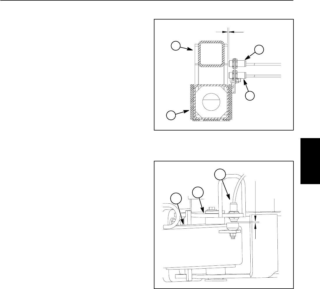
2. The target surface end of proximity switch should be
from 0.110” to 0.170” (2.8 to 4.3 mm) from sensing plate
on sweeper (Figs. 2 and 3).
3. If necessary, loosen jam nuts on switch and adjust
switch location to allow proper clearance between
switch and sensing plate.
4. After adjustment, torque jam nuts from 165 to 195
in--lb (18.7 to 22.0 N--m). After tightening jam nuts,
check that clearance between end of proximity switch
and sensing plate has not changed.
5. After adjustmentiscomplete,makesurethatproxim-
ity switch connector is plugged into sweeper wire har-
ness.
1. Main frame
2. Pitch frame
3. Proximity switch
Figure 2
0.110 to 0.170”
(2.8 to 4.3 mm)
1
3
2
3
1. Main frame
2. Tongue hitch
3. Proximity switch
Figure 3
0.110 to 0.170”
(2.8 to 4.3 mm)
2
1
3
Electrical
System


