Pro Sweep Page 4 -- 17 Electrical System
Control Module
The control module is a solid state electrical device that
receives signal inputs from the remote transmitter and
uses those inputs to control sweeper electrical opera-
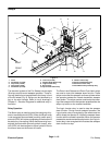
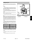
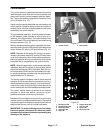
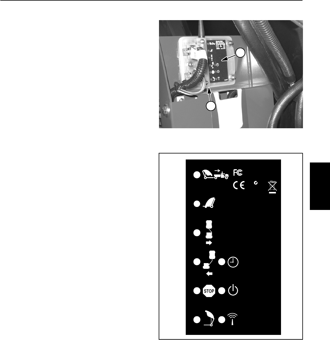
tion. The control module is attached to the frame in front
of the RH wheel (Fig. 15).
Inputs from the remote transmitter are monitored by the
control module. Output to machine relays and hydraulic
solenoid valve coils are controlled based on the inputs
received by the control module.
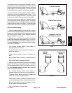
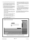
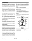
To begin sweeper operation, providing electrical power
to the sweeper power harness is used to turn on or
“wake up” the control module. The control module Time
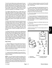
Out and Power LED’s should both be illuminated during
sweeper operation (Fig. 16).
When a remote transmitter button is pressed, the corre-
sponding control module LED should illuminate and the
control module RF activity LED should flicker (Fig. 16).
NOTE: Because of the normal RF activity in the envi-
ronment, the control module RF activity LED may flicker
or be illuminated at any time during machine operation.
Machine operation will only be controlled by the remote
transmitter that is recognized by the control module.
NOTE: When the stop button on the remote transmitter
is pressed, there will be a three (3) s econd delay before
the control module stop LED illuminates. Also, the con-
trol module stop LED will remain illuminated and no oth-
er remote transmitter operations can be performed for
approximately five (5) seconds.
The control module includes a timer to allow machine
operation for 30 minutes after the last control input (e.g.
remote transmitter button pressed). If no inputs are pro-
vided to the c ontrol module during this time period, the
control module will shut off all sweeper electrical power.
The control module does not connect to an external
computer or hand held device, cannot be re--pro-
grammed and does not record any fault data.
Because of the solid state circuitry built into the control
module,thereisnoreliablemethodtotestit.Themodule
may be damaged if an attempt is made to test it with an
electrical test device, such as a digital multimeter.
IMPORTANT: To prevent damage to the Pro Sweep
electrical system, disconnect the electrical power
harness from the tow vehiclebefore performingany
welding on the machine.
1. Control module
2. LED location
Figure 15
2
1
115 --9062
Tested toComply
WithFCCStandards
FORHOMEOROFFICEUSE
Canada
3575APFB1
Model: 07066
N1625
MadeinU.S.A.
1. Sweeper up LED
2. Sweeper down LED
3. Offset right LED
4. Offset left LED
5. Stop LED
6. Hopper dump LED
7. Time out LED
8. Power LED
9. RF activity LED
Figure 16
2
1
4
3
6
5
8
7
9
Electrical
System


