


Pro Sweep Page 5 -- 11 Chassis
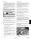
5. Support brush assembly to prevent it from moving.
Follow Servicing the Brush Housing procedure in this
section to remove brush from brush housing.
6. After raising hopper and placing lift cylinder stop, re-
trieve brush assembly from under machine.
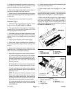
7. Loosen three (3) set screws that secure bearings to
brush shaft. Slide bearing and bearingflangesfromboth
ends of shaft.
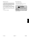
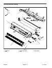
8. Disassemble brush using Figure 6 as a guide.
Installation (Fig. 5)
1. Assemble brush using Figure 6 as a guide. Torque
flange nuts from 27 to 33 ft--lb (37 to 44 N--m).
2. Thoroughly clean brush shaft surface. If necessary,
remove nicks or burrs on shaft with emery cloth or fine
file. Apply antiseize lubricant to shaft.
3. Slide bearing flanges and bearing assembly to each
end of brush shaft with bearing set screws orientated to
outside of brush. Do not tighten bearing set screws at
this time.
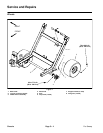
4. Position brush assembly under raised hopper.
5. Slowly lower hopper to position brush assembly to
brush housing (see Servicing the Brush Housing in this
section).
6. Secure bearing flanges to brush housing with car-
riage bolts (item 7), flat washers (item 16) and lock nuts
(item 17). Center brush between bearings.
7. Secure the bearings to the brush shaft as follows:
A. Position the bearing collar so that a set screw is
directlyoppositethesplitinthebearingsleeve.Tight-
en three (3)set screws in bearingso that theyare fin-
ger tight. Make sure that brush is still centered
between bearings.
B. Starting with the set screw that is opposite from
the split in the sleeve, tighten all set screws 1/4 turn.
C. Again, starting with the set screw that is opposite
from the split in the sleeve, tighten all set screws an
additional 1/4 turn.
NOTE: A replacement bearing includes an allen
wrench and torque indicator that can be used to
properly torque bearing set screws.When tightening
set screws, the torque is correct when the long end
of the allen wrench contacts the torque indicator.
D. Finally,starting with the set screwthat isopposite
from the split in the sleeve, torque all s et screws 66
in--lb (7.5 N--m).
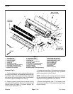
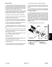
8. Positionsquarekeyinbrushs haft. Slide couplingjaw
onto drive end of brush s haft.
9. Place coupler spider into coupling jaw on brush
shaft.
10.Install hydraulic brush motor to brush housing (see
Hydraulic Brush Motor Installation in the Service and
Repairs section of Chapter 3 -- Hydraulic System).
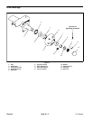
11.Make sure that coupling jaws have a gap between
coupler jaw valleys from 0.830” to 0.930” (21.1 to 23.6
mm). Apply Loctite #242 (or equivalent) to threads of
coupling set screws. Secure coupling jaws to motor
shaft and brush shaft by torquing set screws from 61 to
85 in--lb (6.9 to 9.6 N--m) (Fig. 7).
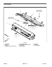
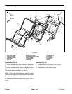
1. Brush
2. Flange nut (2 used)
3. Cap screw (2 used)
4. Key (4 used)
5. Washer (4 used)
6. Brush axle
Figure 6
2
3
4
1
5
6
4
5
27 to 33 in--lb
(37to44N--m)
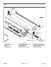
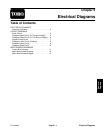
1. Hydraulic brush motor
2. Key
3. Coupling jaw
4. Coupling spider
5. Brush
6. Square key
7. Set screw (2 per jaw)
Figure 7
1
2
3
4
5
6
7
3
61 to 85 in--lb
(6.9 to 9.6 N--m)
Loctite #242
Antiseize
Lubricant
Antiseize
Lubricant
Chassis