Pro Sweep
Page 4 -- 10
Electrical System
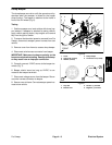
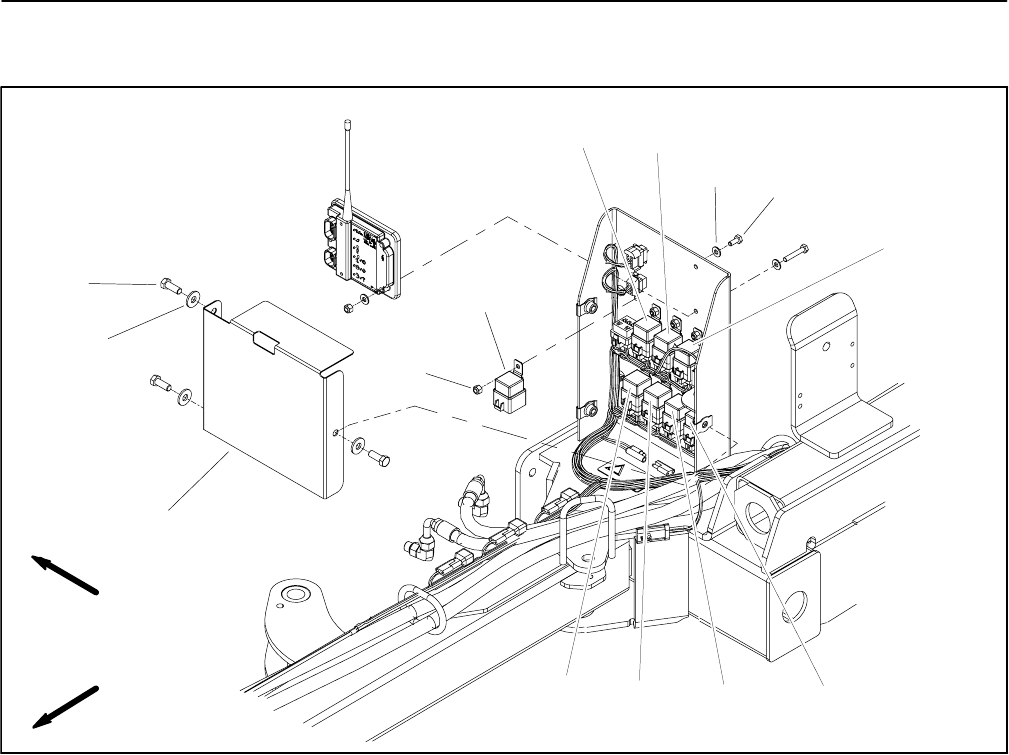
Relays
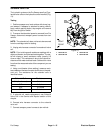
1. Cover
2. Flat washer (3 used)
3. Cap screw (3 used)
4. Cap screw (8 used)
5. Flat washer (8 used)
6. Lock nut (8 used)
7. Hopper Height Select relay
8. Logic Inverter relay
9. Broom relay
10. Up Function Select relay
11. Offset Lockout relay
12. Down Latch Release relay
13. Down Float Latch relay
14. Hitch Home Verify for Dump relay
Figure 8
2
3
6
8
9
10
11
13
1
5
7
12
14
4
FRONT
RIGHT
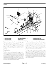
The electrical system of the Pro Sweep includes eight
(8) relays used to c ontrol sweeper operation. These re-
lays are identical and are attached to the frame in front
of the RH wheel (Fig. 8). Relays can be identified by a
tag on the wire harness. Refer to circuit drawings in
Chapter 6 -- Electrical Diagrams for additional relay in-
formation.
Relay Operation
The Broom relay is used to control the energizing of hy-
draulic manifold solenoid (SRV). When the Broom relay
is not energized (broom enable proximity switch open),
solenoid (SRV) will not be energized and the broom will
be stationary (not rotating). When the Broomrelay is en-
ergized (broom enable proximity switch closed), s ole-
noid (SRV) will be energized to allow hydraulic flow to
the broom motor so the broom will rotate.
The Down Latch Release and Down Float Latch relays
are used to control the sweeper down function. These
relays ensure that the sweeper continues to lower when
the operator presses the remote transmitter sweeper
down button.The relays are also used to stop the lower-
ing of the sweeper when the operator presses either the
stop or up button on the remote transmitter.
The Logic Inverter relay is used to stop the sweeper
down function. During normal sweeper operation, the
Logic Inverter r elay is energized by the remote receiver
which allows the operator to initiate the sweeper down
function with the remote transmitter. When the operator
presses the remotetransmitterstop button, theLogic In-
verter relay is de--energized which causes the sweeper
down function to stop.


