


Pro Sweep Hydraulic SystemPage 3 -- 25
2. Relieve sweeper hydraulic system pressure.
3. Clean brush motor and hydraulic connections. Label
hydraulic lines for assembly purposes.
4. Disconnecthydraulichosesfromhydraulic fittings on
brush motor. Allow hydraulic oil to drain from lines into
asuitablecontainer.Putcapsorplugsonopenhydraulic
lines and fittings to prevent contamination.
5. Remove upper coupling cover from brush housing.
6. Support brush motor. Remove two (2) cap screws
(item 13), flat washers (item 6) andlocknuts(item5)that
secure motor to frame. Pull brush motor (with coupling
jaw attached) from the machine.
IMPORTANT: To prevent damage to hydraulic mo-
tor,DONOThitcouplingjawormotorwithahammer
during coupling jaw removal or installation.
7. Loosen set screw that secures coupling jaw to brush
motor shaft. Use puller to remove coupling jaw from mo-
tor shaft. Locate and retrieve woodruff key from motor
shaft.
8. If required, remove hydraulic fittings and O--rings
from the wheel motor. Discard O--rings.
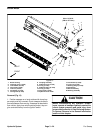
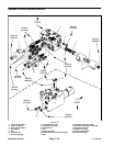
Installation (Fig. 13)
1. If removed, install hydraulic fittings with new O--rings
into the brus h motorports (see Hydraulic Fitting Installa-
tion in the General Information section of this chapter).
2. If coupling jaw was removed from motor, apply anti-
seize lubricant to motor shaft. Position woodruff key into
shaft keyway and slide coupling jaw onto shaft. Make
sure that coupling spider is positioned into coupling jaw
on brush shaft.
3. Align coupling jaw on motor shaft with coupling s pi-
der. Position and support brush motor to the frame.
4. Align motor shaft with brush shaft. Secure brush mo-
tor to frame with two (2) cap screws (item 13), flat wash-
ers (item 6) and lock nuts (item 5). Torque lock nuts from
94 to 116 ft--lb (128 to 157 N--m).
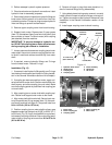
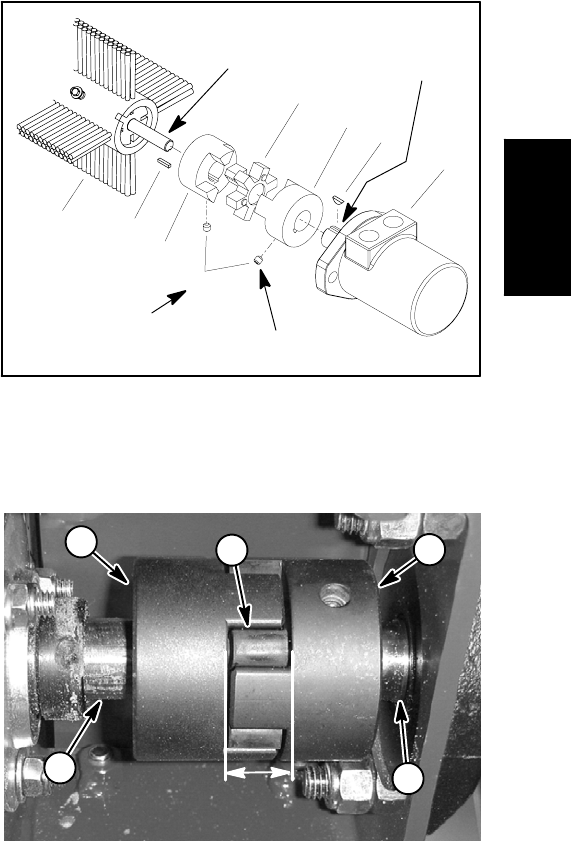
5. Position coupling jaw on motor shaft to allow a gap
between coupler jaw valleys from 0.830” to 0.930” (21.1
to 23.6 mm) (Fig. 15). Apply Loctite #242 (or equivalent)
to threads of coupling set screw. Secure coupling jaw to
motor shaft by torquing set screw from 61 to 85 in--lb
(6.9 to 9.6 N--m).
6. Remove all caps or plugs that were placed on hy-
draulic lines and fittings during disassembly.
7. Using labels placed during motor removal, correctly
install hydraulic hoses to hydraulic fittings on brush mo-
tor. Tighten connections (see Hydraulic Hose and Tube
Installation in the General Information section of this
chapter).
8. Install upper coupling cover to brush housing.
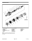
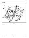
1. Hydraulic brush motor
2. Woodruff key
3. Coupling jaw
4. Coupling spider
5. Brush assembly
6. Square key
7. Set screw
Figure 14
1
2
3
4
5
6
7
3
61 to 85 in--lb
(6.9 to 9.6 N--m)
Loctite #242
Antiseize
Lubricant
Antiseize
Lubricant
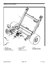
1. Brush shaft
2. Brush coupling jaw
3. Coupling spider
4. Motor coupling jaw
5. Motor shaft
Figure 15
0.830” to 0.930”
(21.1 to 23.6 mm)
1
2
5
43
Hydraulic
System