Pro Sweep
Page 4 -- 14
Electrical System
4. If a proximity switch LED does not function correctly:
A. Disconnect sweeper power harness from tow ve-
hicle. Then, disconnect the proximity switch connec-
tor from the sweeper wire harness. Reconnect
sweeper power harness to tow vehicle.
B. Using a multimeter, verify that the sweeper wire
harness connector terminal for the appropriate wire
has 12VDC whenelectrical powerexists tosweeper
and sweeper is positioned as listed below.
Turn Around Position Switch (hole number 1):
Violetharness wire has 12 VDC when sweeper is
lowered and offset.
Transport Position Switch (number 3): Yellow
harness wire has 12 VDC when sweeper is low-
ered and not offset.
Offset Lockout Switch (number 5): Pink harness
wire has 12 VDC in any sweeper position.
Broom Enable Switch (number 7): Pink harness
wire has 12 VDC in any sweeper position.
Hitch Home Switch: Pink harness wire has 12
VDC in any sweeper position.
C. Make sure that gap between end of proximity
switch and frame sensing plate is from 0.110” to
0.170” (2.8 to 4.3 mm). If necessary, adjustproximity
switch (see Proximity Switches in the Adjustments
section).
D. Make sure that sweeper wire harness ground
wire (black) is closed to ground.
E. If harness wire has system voltage present and
gap is correct but switch LED did not function, re-
place proximity switch. Make sure that switch is
properly adjusted (see Proximity Switches in the Ad-
justments section).
5. After testing is complete, make sure that switch con-
nector is plugged into sweeper wire harness. Connect
sweeper power harness to tow vehicle.
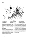
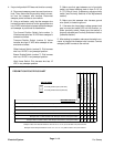
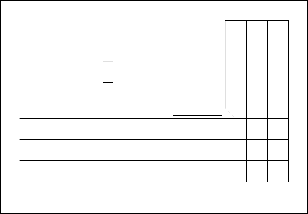
PROXIMITY SWITCH
MACHINE FUNCTION
Sweeper Head Turn Around Position is from 8 1/2” to 10 1/2” (215.9 to 266.7 mm) from Ground
Turn Around Position Switch (hole 1)
Transport Position Switch (hole 3)
Offset Lockout Switch (hole 5)
Broom Enable Switch (hole 7)
HitchHomeSwitch
X
X
O
X
X
X
X
X
O Proximity Switch Open (LED OFF)
Proximity Switch Closed (LED ON)
KEY TO CHART
X
Sweeper in Offset Position with Sweeper Head Below Turn Around Position
Sweeper NOT in Offset Position with Sweeper Head Between Turn Around and Transport Position
Sweeper Head Transport Position is from 13 1/4” to 15 1/4” (336.6 to 387.4 mm) from Ground
Sweeper in Offset Position with Sweeper Head At Turn Around Position
Sweeper NOT in Offset Position with Sweeper Head At Transport Position
OOO
O
O
O
X
X
O
OO
O
Sweeper NOT in Offset Position with Sweeper Head Below Turn Around Position X XXOX
PROXIMITY SWITCH STATUS CHART
Sweeper NOT in Offset Position with Sweeper Head Above Transport Position OXOOO


