


Pro Sweep Hydraulic SystemPage 3 -- 35
IMPORTANT: When removing seal components, be
careful to not scratch or damage piston or head.
6. Remove and discard seal kit components from the
head and piston.
Inspection
CAUTION
Use eye protection such as goggles when using
compressed air
1. Wash all cylinder parts in solvent. Dry parts with
compressed air.
2. Inspect internal surface of tube for deep scratches,
out--of--roundness and bending.
3. Inspect rod, piston and head for excessive pitting,
scoring or wear.
4. If cylinder components are found to be worn or dam-
aged, replace cylinder.
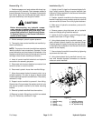
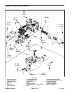
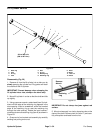
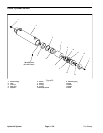
Assembly (Fig. 22)
1. Coat new seal kit components with clean hydraulic
oil.
IMPORTANT: When installing seal components, be
careful to not scratch or damage piston or head.
2. Install new seals to the head and piston.
IMPORTANT: Do not clamp vise jaws against rod
surface.
3. Mount rod securely in a vise by clamping vise on the
clevis of the shaft. Carefully slide head assembly and
piston assembly onto the rod.
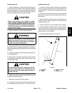
4. Thread lock nut (item 11) onto rod. Torque lock nut
from 250 to 300 ft--lb (339 to 407 N--m).
5. Remove rod assembly from vise.
IMPORTANT: Prevent damage when clamping the
tube into a vise; clamp on the clevis only.
6. Mount tube in a vise so that the rod end tilts up slight-
ly.
IMPORTANT: When installing the head into the
tube, pay careful attention to t he retaining ring slot
in the tube to ensure that the backup ring does not
lodge in the slot.
7. Coat all internal lift cylinder parts with a light coating
of clean hydraulicoil. Slide rod assembly intotube being
careful to not damage the seals.
8. Secure head in tube by installing retaining ring (item
8).
A. Align retaining ring hole in the head with the ac-
cess slot in the tube.
B. Insert the retaining ring hook into the hole and ro-
tate head clockwise until the retaining ring is com-
pletely pulled intothe tube and theends are covered.
C. Apply silicone sealer to tube access slot.
Hydraulic
System