


2.0 General Layout
7
© Baxi Heating UK Ltd 2011
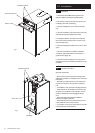
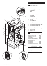
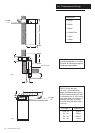
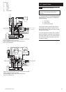
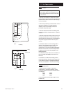
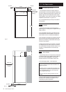
2.1 Layout (Figs. 3, 4, 5 & 6)
1. Condensate Pump
2. Flue Elbow (supplied in std. flue kit)
3. Heat Exchanger
4. Burner
5. Air Box
6. Fan Protection Thermostat - Black
7. Fan Assembly
8. Condensate Trap
9. PCB Housing Assembly
10. Gas Tap
11. Gas / Air Ratio Valve
12. Flow Pipe Connection
13. Return Pipe Connection
14. Flow Temperature Safety Thermostat - Black
15. Flow Temperature Thermistor - Red
16. Flow Switch (dry fire protection)
17. Position of Optional Integral Timer Wiring
18. Pipe Access Panel
19. Manual Air Vent
2
3
4
5
6
7
9
8
10
11
15 14
12
13
16
Fig. 4
Fig. 3
Fig. 5
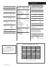
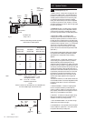
2.2 110Ø Concentric Flues & Optional Extras
KIT PART N
o
Standard Flue Kit 850mm (inc. elbow) 236921
Extended Flue Kit - 1.75M ( inc. elbow) 5111457
Flue Plume Deflector Kit 248167
Terminal Guard (suitable for use with above) 248484
FLUE EXTENSION KITS (110/70)
Flue Extension 250mm 241692
Flue Extension 500mm 241694
Flue Extension 1000mm
(Use two kits for 2M etc.) 241695
Flue Bend x 2 - 45°
(Reduce overall length of flue
by 0.5m when fitting this bend)
241689
Flue Bend - 93° (
Reduce overall length of flue
by 1m when fitting each bend)
241687
VERTICAL FLUE
Vertical Flue Terminal 242802
Vertical Flue Adaptor 5106888
See Section 7.12 for more flue option details
Integral Twin Channel Timer 5117696
Fig. 6
1
17
18
19