


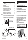
7.0 Site Requirements
19
© Baxi Heating UK Ltd 2011
7.8 Flue
NOTE: Due to the high efficiency of the boiler a plume of
water vapour will be discharged from the flue. This should
be taken into account when siting the flue terminal.
1. The following guidelines indicate the general requirements
for siting balanced flue terminals.
For GB recommendations are given in BS 5440 Pt.1.
For IE recommendations are given in the current edition of I.S.
813 “Domestic Gas Installations”.
2. If the terminal discharges onto a pathway or passageway,
check that combustion products will not cause a nuisance and
that the terminal will not obstruct the passageway.
3. When siting the flue take into consideration the effect the
plume of water vapour may have on neighbours .
4. Adjacent surfaces close to the flue terminal may need
protection from the effects of condensation. Alternatively a flue
deflector kit (part no. 248167) is available.
5. For installation of the flue into an internal corner at the
25mm dimension the flue plume deflector kit (part no. 248167)
must be fitted.
6. * Reduction to the boundary is possible down to 25mm but
the flue plume deflector kit (part no. 248167) must be fitted.
7. If a terminal is less than 2 metres above a balcony, above
ground or above a flat roof to which people have access, then
a suitable terminal guard must be provided.
8. If required a suitable terminal guard (part no. 248484) is
available from Potterton for use with the flue deflector. See
also Section 8.8.
9. For fitting under low soffits and eaves the Plume
Displacement Kit or Flue Deflector Kit is recommended.
IMPORTANT:
• Only ONE 25mm clearance is allowed per installation.
• Under car ports we recommend the use of the plume
displacement kit.
• The terminal position must ensure the safe and
nuisance - free dispersal of combustion products.
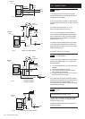
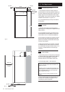
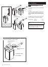
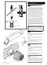
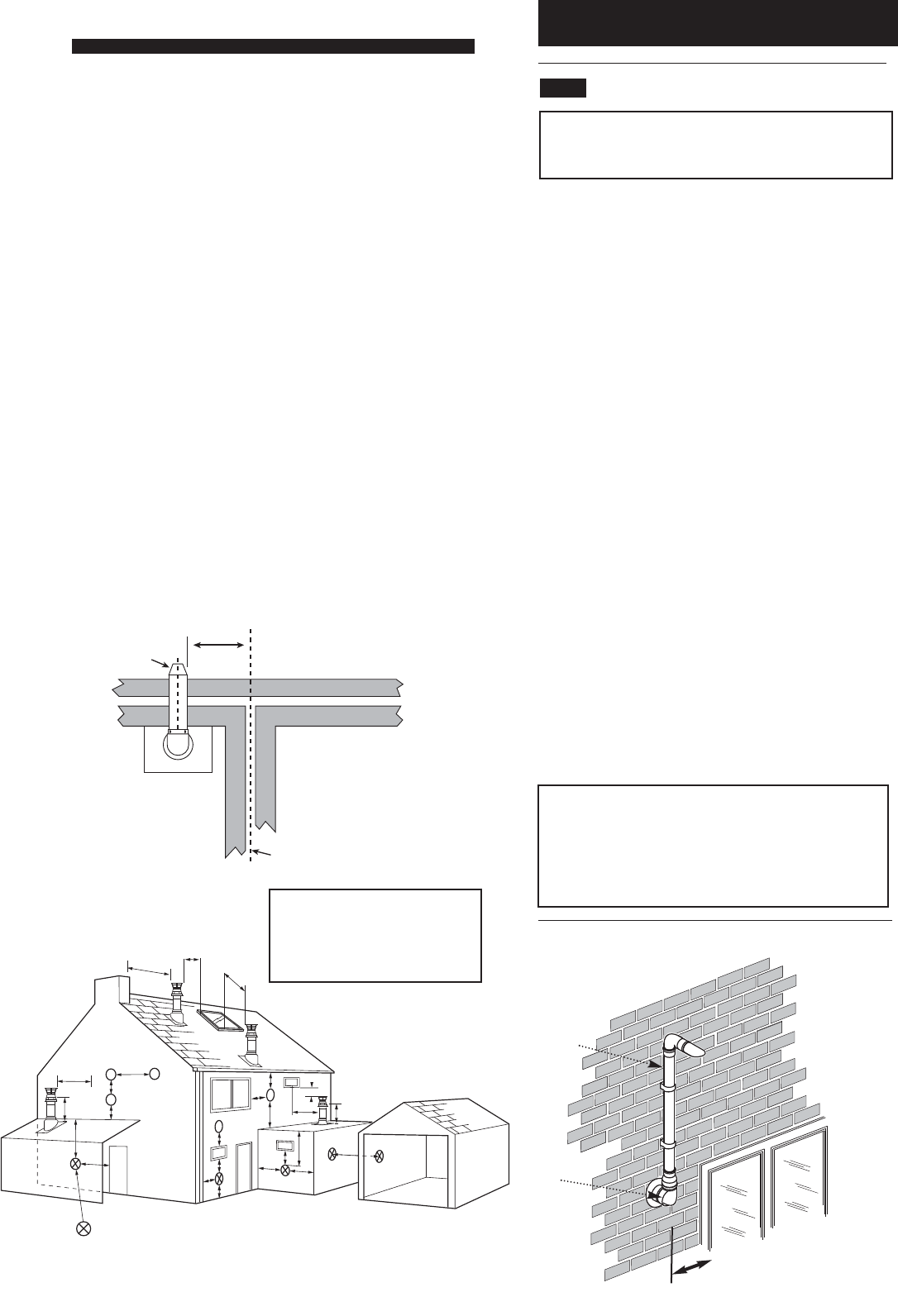
Fig. 16a
300 min
Terminal
Assembly
Top View Rear Flue
Property Boundary Line
NOTE: The distance from a fanned draught boiler terminal
installed parallel to a boundary may not be less than 300mm
in accordance with the diagram below, unless the flue deflector
kit is used (see 7.8.6 opposite)
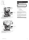
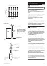
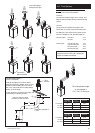
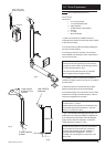
Table. 2
Terminal Position with Minimum Distance (Fig. 17) (mm)
A
a
Directly below an opening, air brick, opening
windows, etc. 300
B
a
Above an opening, air brick, opening window etc. 300
C
a
Horizontally to an opening, air brick, opening window etc. 300
D Below gutters, soil pipes or drain pipes. 25
E Below eaves. 25
F Below balconies or car port roof. 25
G From a vertical drain pipe or soil pipe. 25
H From an internal
(i)
or external
(ii)
corner.
(i)
25
(ii)
115
I Above ground, roof or balcony level. 300
J From a surface or boundary line facing a terminal. 600
K From a terminal facing a terminal (Horizontal flue). 1200
From a terminal facing a terminal (Vertical flue). 600
L From an opening in carport (e.g. door, window)
into the dwelling. 1200
M Vertically from a terminal on the same wall. 1500
N Horizontally from a terminal on the same wall. 300
R From adjacent wall to flue (vertical only). 300
S From an adjacent opening window (vertical only). 1000
T Adjacent to windows or openings on pitched and flat roofs 600
U Below windows or openings on pitched roofs 2000
a
In addition, the terminal should be no nearer than 150 mm to an
opening in the building fabric formed for the purpose of accommodating
a built-in element such as a window frame. See BS 5440 Pt. 1.
*
N
I
I
G
F
M
I
A
A
F
H
J,K
D
E
H
Likely flue positions requiring
a flue terminal guard
C
R
A
I
J,K
I
L
S
B
T
U
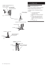
Fig. 17
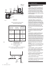
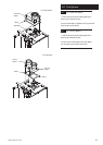
Opening Window
or Door
150mm
MIN.
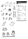
Fig. 17a
Plume
Displacement Kit
Air Inlet
IMPORTANT: If fitting a Plume
Displacement Flue Kit, the air inlet
must be a minimum of 150mm from
any opening windows or doors.
*