


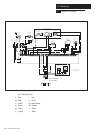

15.0 Changing Components
42
© Baxi Heating UK Ltd 2011
15.1 Changing Components & Preparation
WARNING: The PCB Control and Fan
Assembly are 325 Vdc. Isolate system
controls before access.
IMPORTANT: Ensure that both the gas and electrical
supplies, including Switched and Permanent Live to the
boiler are isolated before any work is started.
The four facia LEDs will be all OFF.
It is important to isolate the electrical supply at the
system isolation switch as it is not possible to do this
on the boiler itself.
Hazardous materials are not used in the construction of
this product, however reasonable care is recommended
- see Section 1.2.
When replacing the combustion box door it is essential
that the retaining screws are tightened fully.
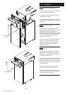
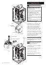
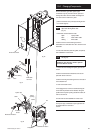
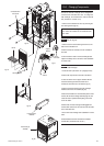
Remove the facia and front door panel.
For the replacement of some components it will be
necessary to drain the boiler. Proceed as follows:-
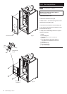
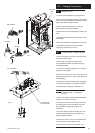
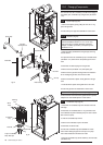
1. Isolate the water circuit and drain the system as
necessary. A drain point is located on the heat
exchanger manifold at the right hand side of the boiler
(Fig. 45) to enable the heat exchanger to be drained.
2. Place a tube on the drain point to drain water away
from the electrics. Turn anticlockwise to open (Fig. 45).
3. After changing a component recommission the boiler
where appropriate and check the inhibitor
concentration (see Section 6.2 and 10.1).
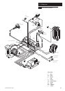
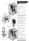
The thermistor, safety thermostat, interface PCB and
the flow switch can be accessed after removal of the
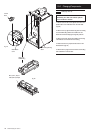
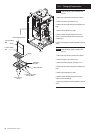
pipe access panel (Fig. 46).
15.2 Flow Temperature Thermistor and
Safety Thermostat
(Fig. 46)
1. The procedure is the same for both the thermistor
and the safety thermostat.
2. Remove the pipe access panel and disconnect the
electrical connections from the sensor.
3. Remove the sensor from the pipe.
4. Fit the new thermistor or safety thermostat and
reassemble in reverse order.
Drain Point
Heat Exchanger
Manifold
Tube
Electrical Connections
Flow Temperature Thermistor (Red)
Safety
Thermostat
(Black)
Fig. 45
Fig. 46
Pipe Access
Panel